Positive electrode plate and non-aqueous electrolyte secondary battery

a technology of positive electrode active material and secondary battery, which is applied in the direction of positive electrode, active material electrode, secondary cell servicing/maintenance, etc., can solve the problems that the thermal decomposition the heat generation of the positive electrode active material cannot be suppressed, so as to achieve the effect of suppressing the increase in resistance of the battery, reducing the cost of the battery and increasing the capacity of the positive electrode active material

Active Publication Date: 2019-04-18
TOYOTA JIDOSHA KK
View PDF7 Cites 1 Cited by
  • Summary
  • Abstract
  • Description
  • Claims
  • Application Information

AI Technical Summary

Benefits of technology

[0004]A positive electrode active material contained in a positive electrode has been demanded to be higher in capacity while increase in resistance of a battery is suppressed. A higher capacity of the positive electrode active material can be achieved, for example, by increasing a ratio of Ni in the positive electrode active material expressed as (LiNiaCobMncO2 (where a+b+c=1)).

Problems solved by technology

Therefore, it is considered that thermal decomposition of the positive electrode active material and heat generation by the positive electrode active material cannot be suppressed.

Method used


Image

  • Positive electrode plate and non-aqueous electrolyte secondary battery
  • Positive electrode plate and non-aqueous electrolyte secondary battery
  • Positive electrode plate and non-aqueous electrolyte secondary battery

Examples


example 1

[0076]1. Preparation of Positive Electrode Plate

[0077]Materials below were prepared.

[0078]Positive electrode active material: NCM

[0079]Conductive material: AB

[0080]Binder: PVDF

[0081]Flame retardant: diammonium phosphate (thermal decomposition temperature: 150° C.)

[0082]Solvent: N-methyl-2-pyrrolidone (NMP)

[0083]Positive electrode current collector: Al foil (a thickness of 15 μm and a width dimension=130 mm)

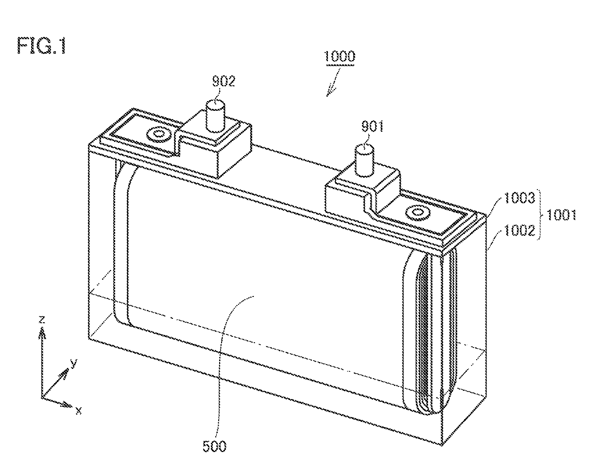
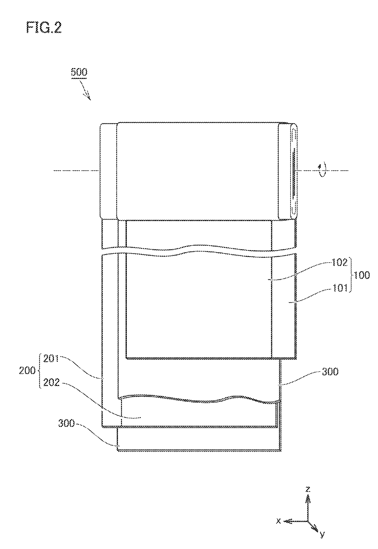
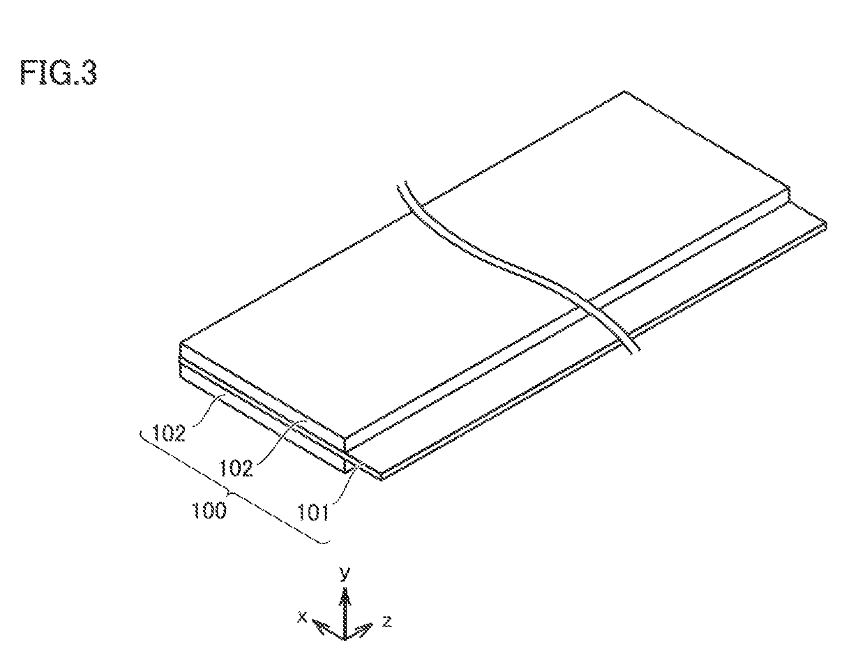
[0084]A paste was prepared by mixing NCM, AB, PVDF, diammonium phosphate, and NMP. A ratio of mixing was set to “NCM:AB:PVDF:diammonium phosphate=94:1:1:4” at a mass ratio. Positive electrode composite material layer 102 was formed by applying the paste to a surface of positive electrode current collector 101 and drying the paste. Positive electrode composite material layer 102 (dried, on one surface) had a weight per unit area of 25 mg / cm2. Positive electrode composite material layer 102 had a width dimension of 110 mm. A concentration of P contained in positive electrode composi...

examples 2 to 12

[0114]Battery 1000 was manufactured as in Example 1 except for change in value (B / A) calculated by dividing porosity B (%) of positive electrode composite material layer 102 by content A (mass %) of P and S contained in positive electrode composite material layer 102 as shown in Table 1 below.

examples 13 to 16

[0115]Battery 1000 was manufactured as in Example 1 except for change in flame retardant contained in positive electrode composite material layer 102 and change in difference between thermal decomposition end temperature X of the electrolyte solution and thermal decomposition temperature Y of the flame retardant (which will simply also be denoted as “X−Y” below) as shown in Table 1 below.


PUM

PropertyMeasurementUnit
thermal decomposition temperatureaaaaaaaaaa
temperatureaaaaaaaaaa

Abstract

A positive electrode plate includes a positive electrode composite material layer. The positive electrode composite material layer contains at least a positive electrode active material and a flame retardant. The flame retardant contains phosphorus (P) or sulfur (S). The flame retardant has a thermal decomposition temperature not lower than 80° C. and not higher than 210° C. A value calculated by dividing a porosity (%) of the positive electrode composite material layer by an amount (mass %) of P and S contained in the positive electrode composite material layer is not smaller than 5 and not greater than 5000.

Description

[0001]This nonprovisional application is based on Japanese Patent Application No. 2017-199197 filed with the Japan Patent Office on Oct. 13, 2017, the entire contents of which are hereby incorporated by reference.BACKGROUNDField[0002]The present disclosure relates to a positive electrode plate and a non-aqueous electrolyte secondary battery.Description of the Background Art[0003]Japanese Patent Laying-Open No. 2010-251217 discloses containing a flame retardant such as melamine polyphosphate (MPP) in a positive electrode composite material layer of a lithium secondary battery.SUMMARY[0004]A positive electrode active material contained in a positive electrode has been demanded to be higher in capacity while increase in resistance of a battery is suppressed. A higher capacity of the positive electrode active material can be achieved, for example, by increasing a ratio of Ni in the positive electrode active material expressed as (LiNiaCobMncO2 (where a+b+c=1)).[0005]With increase in rat...

Claims


Application Information

Patent Timeline
Patent Type & Authority Applications(United States)
IPC IPC(8): H01M4/62H01M10/42
CPCH01M4/628H01M10/4235H01M2004/028H01M4/62H01M10/05Y02E60/10
Inventor TORITA, KOJIOCHIAI, AKIHIROFUKUMOTO, YUSUKESHIMAMURA, HARUNARI
Owner TOYOTA JIDOSHA KK
Why Eureka
Try Eureka