
Bispectral peroperative optical probe

Inactive Publication Date: 2008-11-27
COMMISSARIAT A LENERGIE ATOMIQUE ET AUX ENERGIES ALTERNATIVES
View PDF4 Cites 21 Cited by
  • Summary
  • Abstract
  • Description
  • Claims
  • Application Information

AI Technical Summary

Benefits of technology

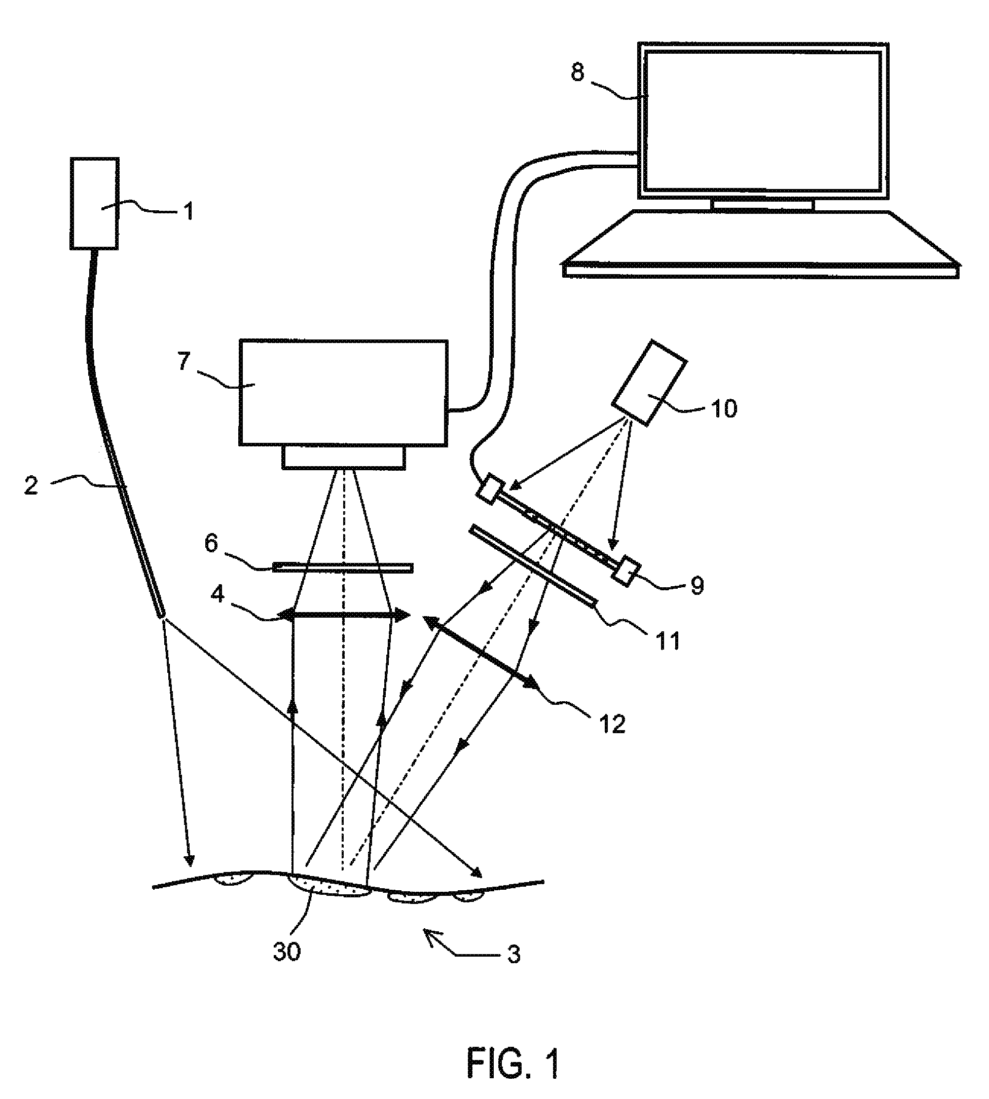
[0015]The object of the invention is to overcome the above disadvantages. To this end, the optical probes of the fluorescence type according to the invention have dual lighting. The first is necessary for achieving the fluorescence of the marked areas and for obtaining an image exploitable by a camera. The second is necessary for illuminating or spotlighting the marked areas with visible light, while leaving the unmarked areas in shadow, thus making the surgeon's work easier.
[0018]The viewing comfort for the surgeon is increased. He no longer needs to look back and forth between his computer screen and the patient's body;

Problems solved by technology

This operation takes time and sometimes remains incomplete, since some affected areas are invisible to the naked eye or are insufficiently differentiated to be recognized by the surgeon.
In this case, the visual field is very substantial and does not allow high resolutions to be obtained.
However, these probes of the fluorescence type have some disadvantages.
Consequently, he cannot get his surgical manoeuvre to coincide precisely with the diseased cells he wishes to remove.

Method used


Image

  • Bispectral peroperative optical probe
  • Bispectral peroperative optical probe
  • Bispectral peroperative optical probe

Examples


first embodiment

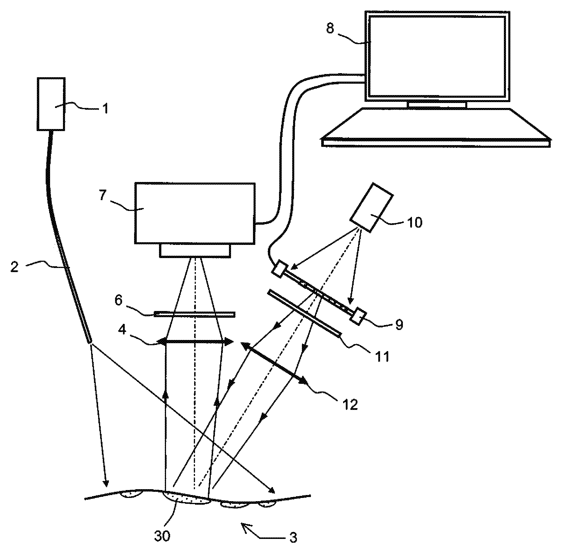
[0044]FIG. 1 is a schematic representation of a probe according to the invention, designed according to the It comprises essentially the elements described below.

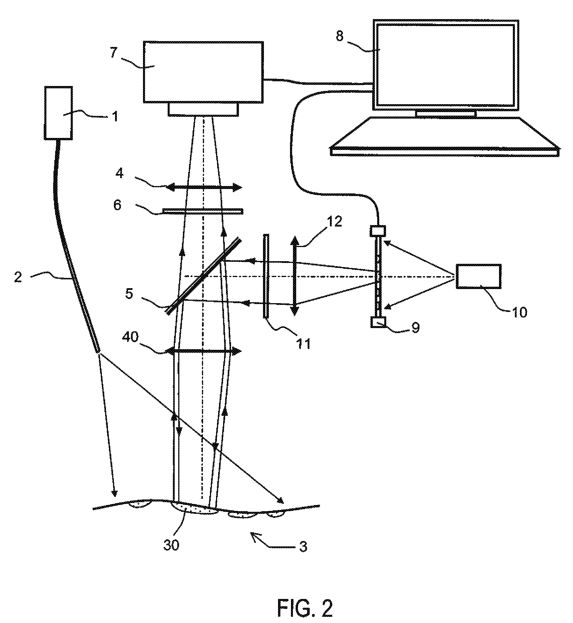
[0045]A first light source 1 emits a first light beam intended to illuminate a biological tissue surface 3, of which at least one area 30, the marked area, has previously been fixed by a fluorescent marker. The techniques for marking living tissue are well known, moreover, and do not fall within the scope of this description. The beam must be emitted at a first wavelength corresponding substantially to the wavelength of excitation of the marking fluorophore. This effect can be obtained using various sources. Thus, the source can be a laser, a light-emitting diode or an incandescent lamp. It can comprise auxiliary optical devices for guiding or directing the light beam in order to improve its light distribution on the illuminated surface. Thus, by way of example, FIG. 1 shows a fibre optic 2 permitting transport of light fr...

second embodiment

[0062]a probe according to the invention is depicted in FIGS. 3 and 4. The probe in FIG. 3 comprises essentially the elements described below:

[0063]A first light source 1 emitting a first light beam intended to illuminate a biological tissue surface 3 at a first wavelength. Under the effect of the excitation light, the fluorophore emits at a second wavelength.

[0064]A first optical device of the camera type, comprising a first lens 4 and a photosensitive surface 7, forms a first image of the biological tissue surface 3 on the photosensitive surface 7. As in the preceding embodiments, this first device can comprise a filter 6.

[0065]This first image can be processed by suitable image-processing means 8 with which it is possible to reveal the marked areas present in the image and to display them on a computer screen or a monitor.

[0066]A second optical device comprising at least a second light source 13 emitting a second beam at the first wavelength and arranged in such a way as to illum...


PUM


Abstract

The general field of the invention is that of peroperative optical probes designed to assist surgeons in performing medical procedures. The optical probes of the fluorescence type according to the invention are designed to be used on living tissues where the diseased areas have been marked by a fluorescent marker. They have dual lighting. The first situated in the red or near-infrared spectrum is necessary for achieving the fluorescence of the marked areas and for obtaining an image exploitable by a camera. The second situated in the visible spectrum is necessary for illuminating the marked areas with visible light, thus making the surgeon's work easier. The visible lighting can be punctiform or can be provided by an image projector. In the latter case, the projected image illuminates only the diseased areas.

Description

RELATED APPLICATIONS[0001]The present application is based on, and claims priority from, French Application Number 07 03738, filed May 25, 2007, the disclosure of which is hereby incorporated by reference herein in its entirety.[0002]1. Field of the Invention[0003]The field of the invention is that of peroperative optical probes designed to assist surgeons in performing medical procedures.[0004]2. Description of the Prior Art[0005]Surgeons use optical probes that can be positioned over a patient. The optical probes function with visible light in order to illuminate the biological tissues on which the surgeons are operating. These probes are notably used for detection and elimination of certain tumours. These optical probes act as a microscope, and they are traditionally connected to a computer for displaying the biological tissues illuminated by the probe. Using a simple enlarged image of the biological tissues, the surgeon's experience is critical in determining the difference betw...

Claims


Application Information

Patent Timeline
IPC IPC(8): A61B5/00
CPCA61B5/0059A61B19/50A61B19/52A61B19/5212A61B19/5223A61B2019/5441A61B90/36A61B90/361A61B34/10A61B90/20A61B2090/3941
Inventor BOUTET, JEROMEPELTIE, PHILIPPE
Owner COMMISSARIAT A LENERGIE ATOMIQUE ET AUX ENERGIES ALTERNATIVES
Learn More