Encryption Via Induced Unweighted Errors

Active Publication Date: 2008-11-27
HARRIS CORP
View PDF99 Cites 54 Cited by
  • Summary
  • Abstract
  • Description
  • Claims
  • Application Information

AI Technical Summary

Benefits of technology

[0009]A method is provided for encrypting data. The method is based on the difficulty in mapping error statistics between errors induced in residues and the corresponding errors resulting when residue number systems are mapped into a weighted number system. This difficult error mapping masks the characteristics of the method

Problems solved by technology

The method is based on the difficulty in mapping error statistics between errors induced in residues and the corresponding errors resulting when residue number system

Method used


Image

  • Encryption Via Induced Unweighted Errors
  • Encryption Via Induced Unweighted Errors
  • Encryption Via Induced Unweighted Errors

Examples


Example

EXAMPLE 1

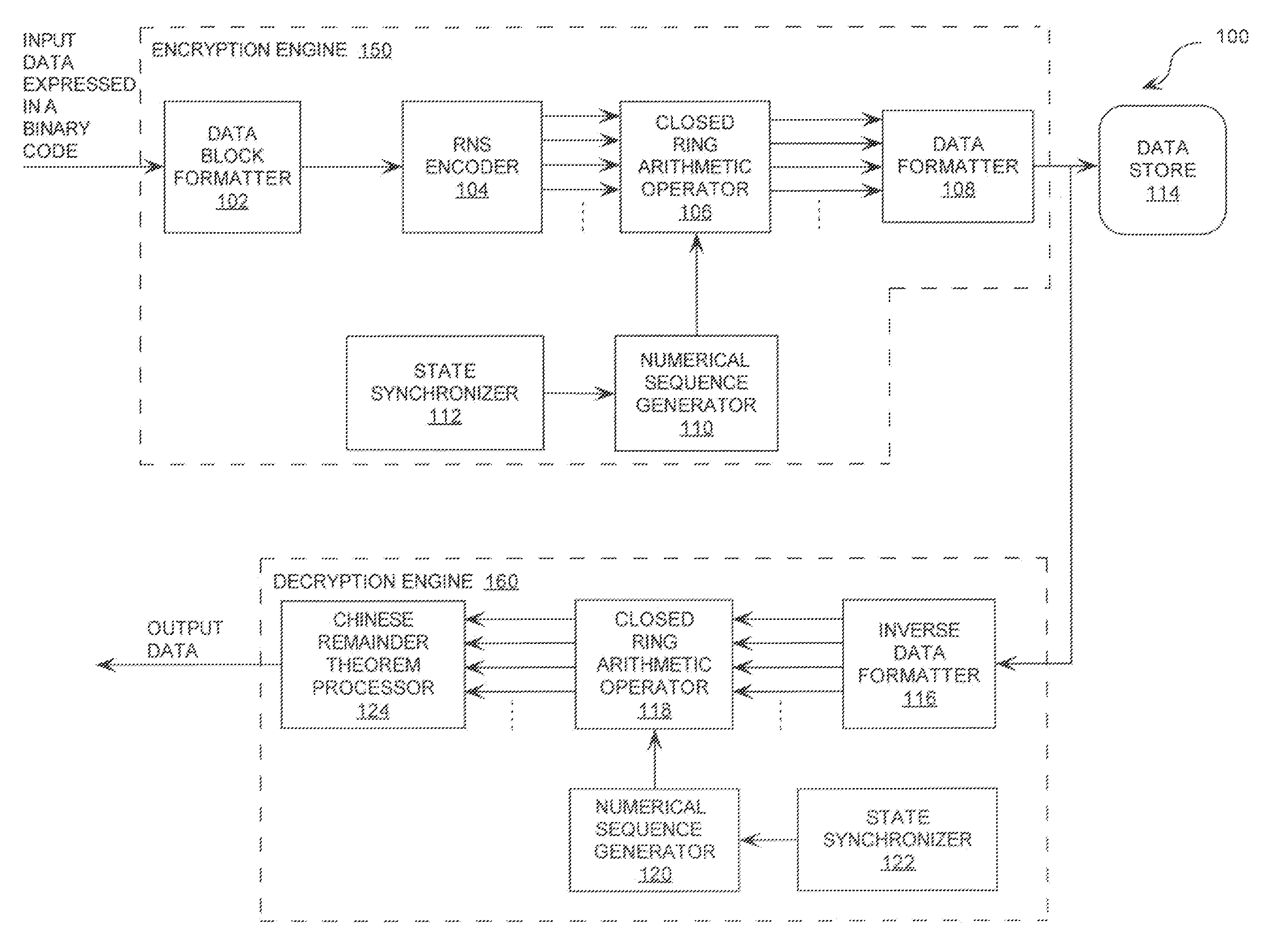
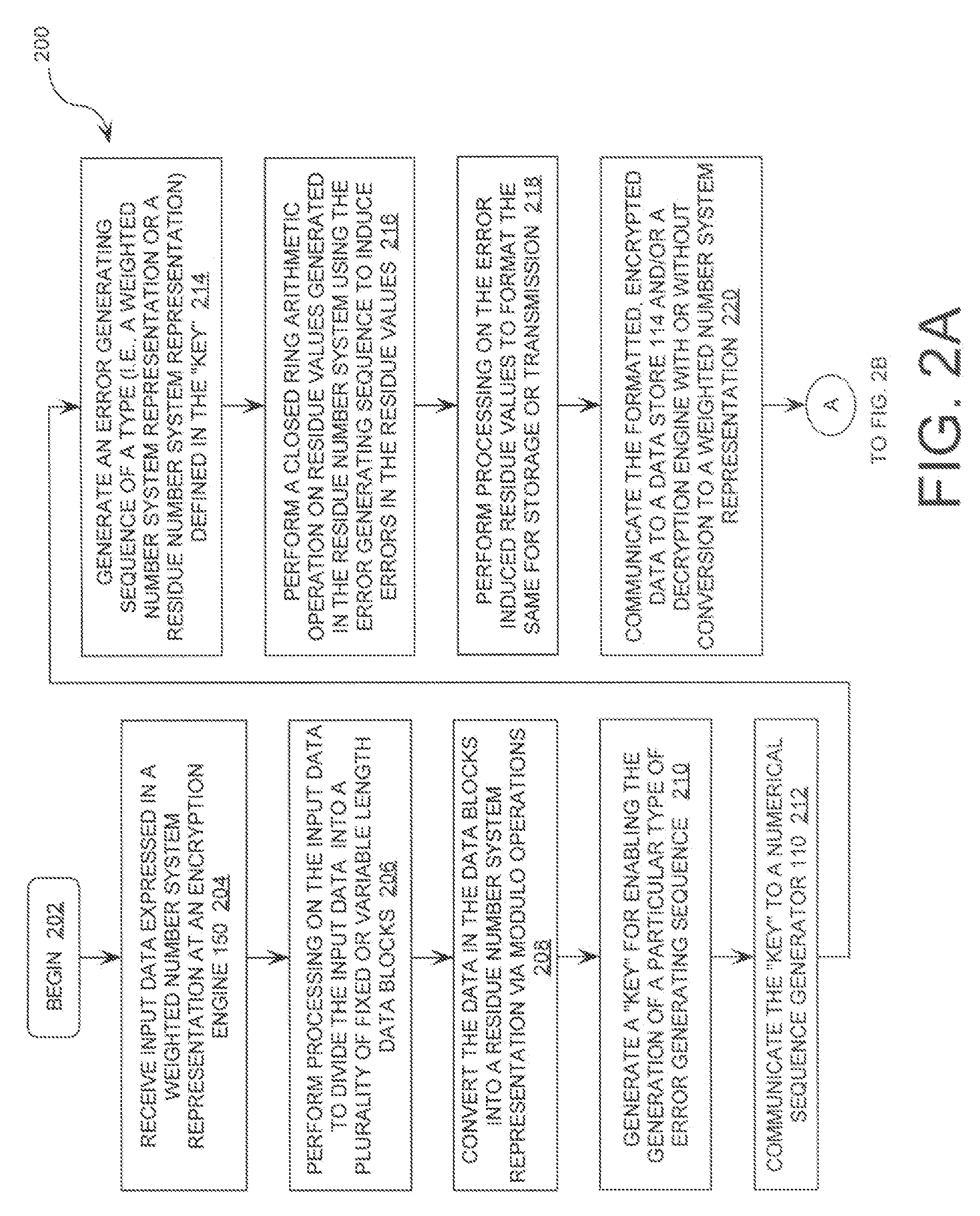
[0026]A first data block is comprised of a binary bit sequence 00001001 representing a horizontal tab, the tenth character of the ASCII character set. As will be understood by a person skilled in the art, the binary bit sequence 00001001 has a decimal value of nine (9). As the Extended ASCII character set has 256 possible values with decimal values from zero (0) to two hundred fifty-five (255) and corresponding binary values from 00000000 to 11111111, the moduli set must supply a dynamic range M=m0, m1, . . . mP-1. P is the number of moduli of at least two hundred fifty-five (255). Three (3) moduli m0, m1, m2 are selected to have values of seven (7), eight (8), and nine (9). This gives a dynamic range of five hundred four (504). Accordingly, the RNS representation of the data in the first block can be computed using Equation (1).

R={Vbbs modulo m0, Vbbs modulo m1, Vbbs modulo m2}   (1)

where R is a residue value 3-tuple for the data in a data block. Vbbs is a value of a bina...

Example

EXAMPLE 2

[0041]Briefly, an input data “the quick brown fox” is generated and converted into a residue number system representation using modulo operations. The residue number system employed is selected to have moduli three (3), five (5), and nineteen (19). Thereafter, a manipulation in residue space is performed by simply flipping the least significant bit (LSB) in the mod three (3) moduli illustrating the principle that a very predictable manipulation of the same bit in residue space

%% Define primes%p(1) = 3;p(2) = 5;p(1) = 19;%% Calculate M%capm = prod(p);%% Define b's%b(1) = 2;b(2) = 3;b(3) = 14;%% Define M / p's%mop(1) = 5*19;mop(2) = 3*19;mop(3) = 3*5;%% Define input string%str =’The quick brown fox’:seq = uint8(str);intct = length(seq);%%Begin conversion into residue space%resarr = zeros(3,intct);for ind = 1:intct for ind1 = 1:3  resarr(ind1,ind) = mod(seq(ind),p(ind1)); endend%% Insert encryption fcn here.%for ind = 1:intct bv = dec2bin(resarr(1,ind),2); if bv(1) == ‘0’  bv(1...

Example

EXAMPLE 3

[0043]Briefly, an input data is generated and converted into a residue number system representation using modulo operations. The input data includes:

“In classical physics, due to interference, light is observed to take the stationary path between two points; but how does light know where it's going? That is, if the start and end points are known, the path that will take the shortest time can be calculated. However, when light is first emitted, the end point is not known, so how is it that light always takes the quickest path? In some interpretations, it is suggested that according to QED light does not have to—it simply goes over

Physically, QED describes charged particles (and their antiparticles) interacting with each other by the exchange of photons. The magnitude of these interactions can be computed using perturbation theory; these rather complex formulas have a remarkable pictorial representation as Feynman diagrams. QED was the theory to which Feynman diagrams were f...


PUM


Abstract

A method for encrypting data is provided. The method includes formatting data represented in a weighted number system into data blocks. The method also includes converting the data blocks into a residue number system representation. The method further includes generating a first error generating sequence and inducing errors int he data blocks after converting the data blocks into a residue number system representation. It should be understood that the errors are induced in the data blocks by using the first error generating sequence. After inducing errors into the data blocks, the data of the data blocks is formatted into a form to be sorted or transmitted. The method also includes generating a second error generating sequence synchronized with and identical to the first error generating sequence and correcting the errors in the data blocks using an operation which is an arithmetic of a process used in inducing errors.

Description

BACKGROUND OF THE INVENTION [0001]1. Statement of the Technical Field[0002]The invention concerns cryptography. More particularly, the invention concerns a cryptographic system that encodes data by combining an input signal in a residue number system representation with an error generating sequence.[0003]2. Description of the Related Art[0004]There are many methods known in the art for encrypting data prior to the data's transmission over a communications network. One such method involves receiving an input signal at a cryptographic device. The input signal is expressed in a binary number system representation, i.e., characters of the English language are represented by a sequence of bits. Each bit of the sequence has a zero (0) or a one (1) value. The method also involves generating an encryption sequence. The encryption sequence can be a pseudo-random number sequence generated using a highly non-linear method. The method further involves inducing changes in the input signal using ...

Claims


Application Information

Patent Timeline
IPC IPC(8): G06F11/00
CPCH04L9/12H04L2209/34H04L9/0656
Inventor CHESTER, DAVID B.MICHAELS, ALAN J.
Owner HARRIS CORP
Why Eureka
Try Eureka