Method of forming a recess in a work

a recess and work technology, applied in the field of recess forming, can solve the problems of deterioration of flatness beyond repair, serious problems, and worsening of punch durability, and achieve the effects of reducing stress on work, easy cutting, and easy formation

Active Publication Date: 2008-12-04
NAKAMURA IND MFG CO LTD
View PDF85 Cites 3 Cited by
  • Summary
  • Abstract
  • Description
  • Claims
  • Application Information

AI Technical Summary

Benefits of technology

[0020]According to the method of forming a recess in a work according to the present invention, the work is carved and a thin cutting fin is vertically formed by the cutting tool. When the thin cutting fin is then cut and separated by the horizontal motion of the cutting tool, stress on the work is minimized and cutting can be readily performed due to the thinness of the cutting fin. The recess is formed in the work by the cutting tool and can therefore be readily formed even when the area of the recess is wide.
[0021]The width of the cutting tool is formed to be equal to the width of the recess, whereby a recess having the same width as the width of the cutting tool can be readily formed in a prescribed location on the work. The longitudinal length can be set as desired by the number of repetitions of the fin-forming step and the cutting step.
[0022]In the fin-forming step, the cutting fin is formed so that the proximal end is thick, whereby at least both sides of the proximal end of the cutting fin are made to protrude. The scrap resulting from cutting the cutting fin in the cutting step is therefore sandwiched between internal walls of the recess. The scraps are therefore retained within the recess, and scattering of the scraps can be prevented. As a result, breakage, damage, and other problems occurring on the readily-damaged blade due to the adherence of scraps to the cutting tool or the work can be prevented in advance.
[0023]The width of the cutting tool is formed to be smaller than the width of the recess, the fin-forming step and the cutting step are repeated, and a narrow first recess is formed. A second narrow recess is then formed adjoining the first recess, and recesses in a plurality of rows are then formed as necessary, whereby a recess having a large area can be readily formed. The use of a cutting tool having a smaller width than the recess allows the work to be cut using minor force and allows the stress on the work to be further alleviated.
[0024]A channel is formed in advance at one end of the planned location for forming the recess in the work, and the fin-forming step and the cutting step are repeated from this channel using the cutting tool, whereby the corner part between the internal wall and the bottom surface of the recess can be formed at a right angle.
[0025]Fins are formed having the proximal end linked to the work, whereby the fins can be prevented from falling away until the blade part of the cutting tool reaches a prescribed depth. A slanting worked surface is formed due to this formation of the fins. The fin-forming step and the cutting step are then repeated in sequence using the cutting tool, whereby a recess having a prescribed depth and area can be formed in the work. Once the recess has been formed, the linked fins join the scraps when the external shape of the work is cut to the prescribed shape. The thin, light fins therefore do not scatter, and breakage, damage, or other adverse occurrences due to scraps or fins adhering to the work or the blade part of the cutting tool can be prevented in advance.

Problems solved by technology

A protrusion forms on the other side of the metal plate due to the pressure on the recess, and flatness deteriorates beyond repair.
As a result, the effect of the residual stress is that the recess in particular will warp due to changes over the course of time, and therefore changes in dimensions may occur, causing serious problems from a quality standpoint.
A high-power press is necessary, and the durability of the punch will worsen.
Inevitable problems of increasing cost are therefore presented.
The etching therefore requires large amounts of time, and this method is therefore unsuitable for mass production and involves inevitable problems of cost increases.
Etching also does not allow the dissolution of each portion to be controlled separately, and problems are therefore presented in that dimensional accuracy is poor and practical applications are limited.

Method used


Image

  • Method of forming a recess in a work
  • Method of forming a recess in a work
  • Method of forming a recess in a work

Examples


embodiment 1

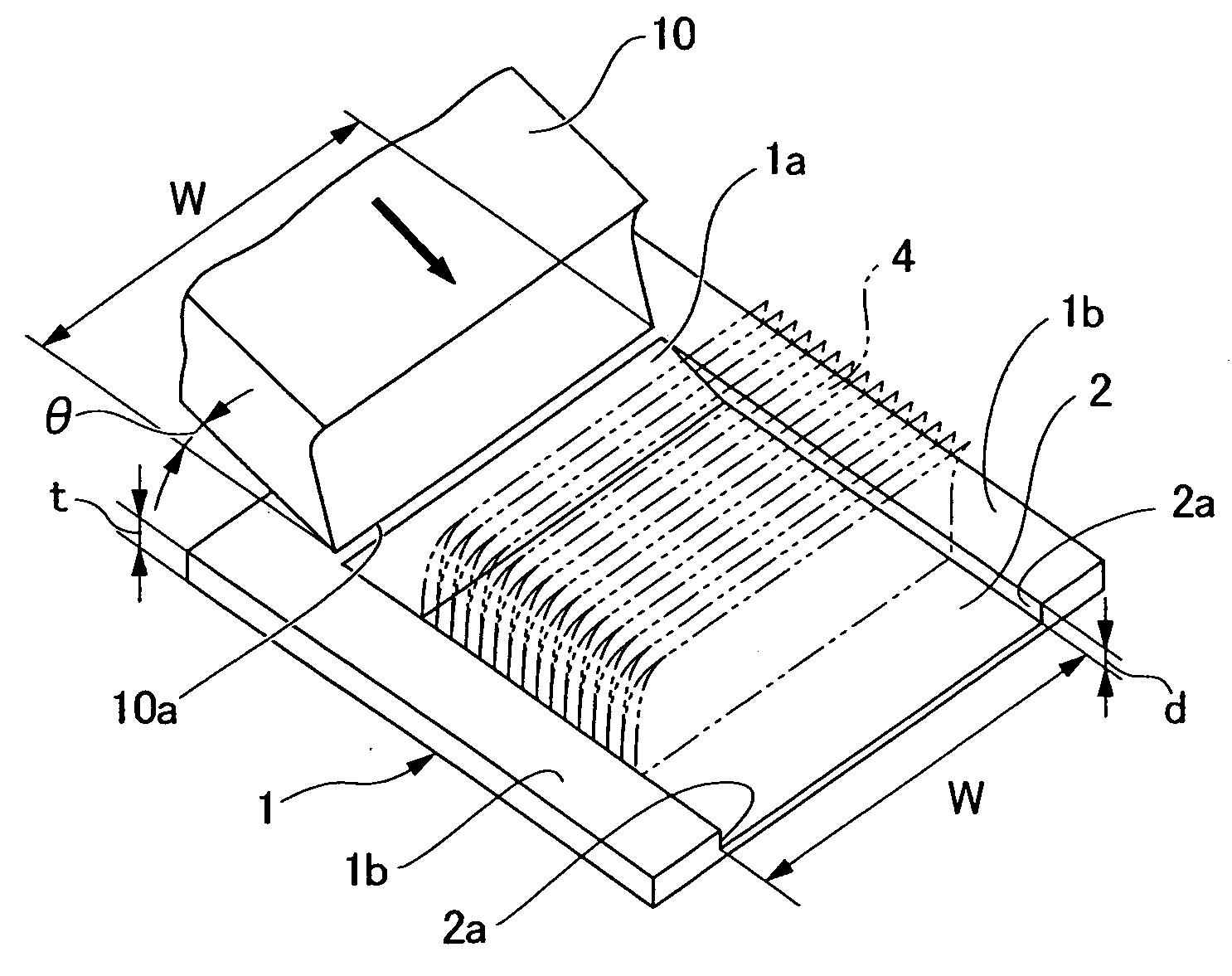
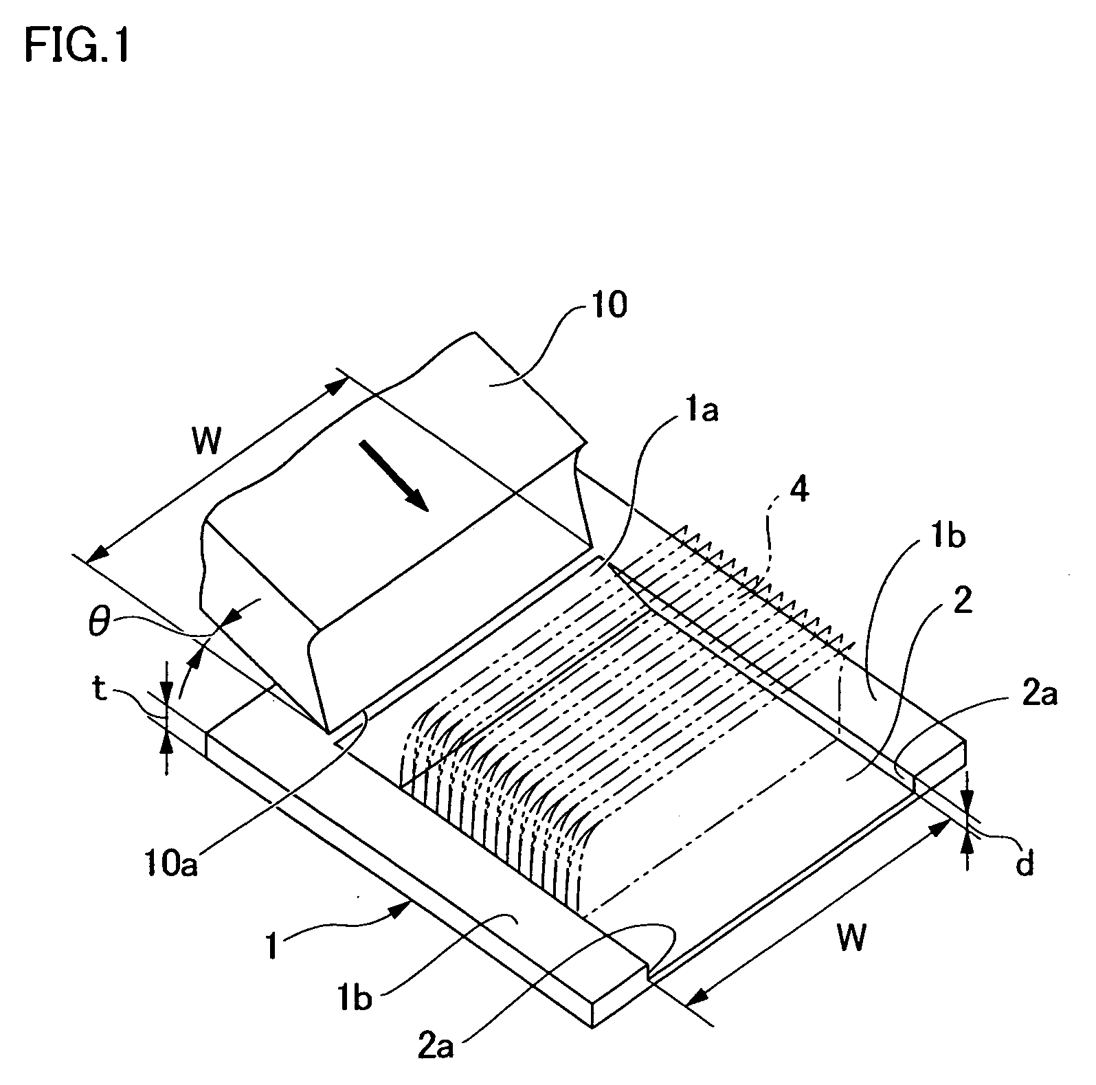
[0040]FIG. 1 shows the configuration of a work 1 in which a recess 2 is formed. The material used in the work 1 is iron, aluminum, copper, stainless steel, other metals, or engineering plastic or another synthetic resin that can be cut. The work 1 is preferably configured in the shape of a flat plate, block, or sphere formed to allow the formation of the recess 2.

[0041]The work 1 shown in FIG. 1 is a metal plate that can be cut and that has been formed into a square shape having a thickness t ranging from 0.2 to several millimeters. The recess 2 is formed on one side of the work 1 and has a width W that is smaller than the width of the work 1 and a depth d that is smaller than the thickness t. The recess 2 is formed by a cutting tool 10. In the work 1 shown in FIG. 1, the forward-end side of the recess 2 is opened, and a slanted worked surface 1a is formed on the rearward-end side.

[0042]The cutting tool 10 is formed having a blade part 10a extending in a direction perpendicular to t...

embodiment 2

[0052]A method was described above in Embodiment 1 in which the recess 2 having the prescribed width W was formed using the cutting tool 10 set to have the same width W, but the steps for forming the recess are preferably repeated a plurality of times depending on the material and hardness of the work 1 and the capabilities of the moving apparatus, or when forming a wide recess. FIG. 6 shows an example application for such instances.

[0053]In FIG. 6, a width W10 of the cutting tool 10 is set to be smaller than a width W2 of the recess 2 of the work 1. The width W10 of the cutting tool 10 in this instance is preferably set narrow so as to be a fraction of the width W2 of the recess 2. The width in the example in FIG. 3 is set to be one half of the width of the recess 2. The width W10 of the cutting tool 10 may not necessarily need to be set as a fraction if a neighboring second recess 2d is to be formed overlapping an initially formed recess 2c.

[0054]As shown on the right side of FIG...

embodiment 3

[0055]FIGS. 7(A) through 7(F) show a method for forming in advance the worked surface 1a when forming the recess 2 from the planned location of the recess-forming surface located on the upper surface of the work 1. First, as shown in FIG. 7(A), the blade part 10a of the cutting tool 10 is moved in the carving direction at the angle θ and is inserted so as to cut into one end of the planned location of the work 1. A small fin 1b is thereby made to rise from the upper surface of the work 1. The cutting tool 10 is then moved in the carving direction from a position set apart from the fin 1b, and the next fin 1b is formed. The formation of the fin 1b is repeatedly performed thereafter. A plurality of the fins 1b are formed until eventually the blade part 10a of the cutting tool 10 reaches the depth d of the planned recess 2, as shown in FIG. 7(B). As a result, a worked surface 1c is formed on one side below the bottom surface of the cutting tool 10. The direction of movement of the cutt...


PUM

PropertyMeasurementUnit
angleaaaaaaaaaa
thicknessaaaaaaaaaa
depthaaaaaaaaaa

Abstract

In a method of forming a recess in a work, a work (1) in which the recess is to be formed is a material that can be cut. A cutting tool (10) for forming the recess is held by a moving apparatus at a prescribed angle relative to the work (1). In a fin-forming step, the cutting tool (10) is moved in a carving direction for carving the work (1) at the prescribed angle, and a thin cutting fin (3) is vertically formed. In a cutting step, the cutting tool (10) is moved in the horizontal direction, and the cutting fin 3 is cut and separated from the work 1. The fin-forming step and the cutting step are repeatedly performed in sequence, whereby a recess (2) having a prescribed depth d and area is formed in the work (1). A recess having the prescribed depth can be readily formed in the surface of the work while applying little stress, even when the area is large.

Description

TECHNICAL FIELD[0001]The present invention relates to a method of forming a recess, wherein a recess having a prescribed depth is formed in the surface of a work that is composed of a metal, a synthetic resin, or another material that can be cut.BACKGROUND ART[0002]Methods for forming a concave part having a prescribed shape in the surface of a work composed of metal, synthetic resin, or another material include pressing methods in which a press is used, or chemical etching methods. Pressing methods in which a press is used are generally employed. In these methods, the punch of the press is pressed downwards onto one side of a metal plate having a prescribed thickness, and a recess having a prescribed shape is formed in the metal plate so as to leave a prescribed thickness at the bottom.[0003]In chemical etching methods, a recess is generally formed in a metal plate from one side by well-known chemical etching processes.[0004]However, among the aforedescribed conventional methods, p...

Claims


Application Information

Patent Timeline
Patent Type & Authority Applications(United States)
IPC IPC(8): B21D28/00
CPCB23D5/00B23D79/00B26D3/08Y10T409/502624Y10T409/501148Y10T409/506396Y10T409/50082B26D3/28B21J5/068Y10T83/0304
Inventor MIYAHARA, HIDEYUKI
Owner NAKAMURA IND MFG CO LTD
Why Eureka
Try Eureka