Data collection device enclosure

a data collection device and enclosure technology, applied in the field of imaging devices and data collection devices, can solve the problems of obscuring keypad symbols and display windows, data collection devices are not constructed, and solvents that are normally used in disinfectants have a tendency to attack the plastic from which various equipment is made, etc., to achieve capture and manipulate images

Active Publication Date: 2008-12-04
HAND HELD PRODS
View PDF30 Cites 9 Cited by
  • Summary
  • Abstract
  • Description
  • Claims
  • Application Information

AI Technical Summary

Benefits of technology

[0030]In an embodiment, the data collection device for which the enclosure of the invention is provided comprises a data imaging device, with the data transferal portion of the dice comprising an imaging portion. For this embodiment, the second portion of the enclosure is constructed and arranged for transmission of light to the imaging portion of the imaging device, the second portion including a region having an optical quality enabling the ima

Problems solved by technology

However, solvents that are normally used in disinfectants have a tendency to attack the plastic from which various equipment is made, such as the housings of such equipment, as well as obscuring keypad symbols and display windows.
However, even if the components and graphics are successfully shielded from attack, a problem with known cleaning/sterilizing regimes is that data collection devices are not constructed so that they can be easily or thoroughly cleaned and sterilized.
Because of such equipment including a variety of surfaces and contours, as well as movable control mechanisms, wiping th

Method used


Image

  • Data collection device enclosure
  • Data collection device enclosure
  • Data collection device enclosure

Examples


first embodiment

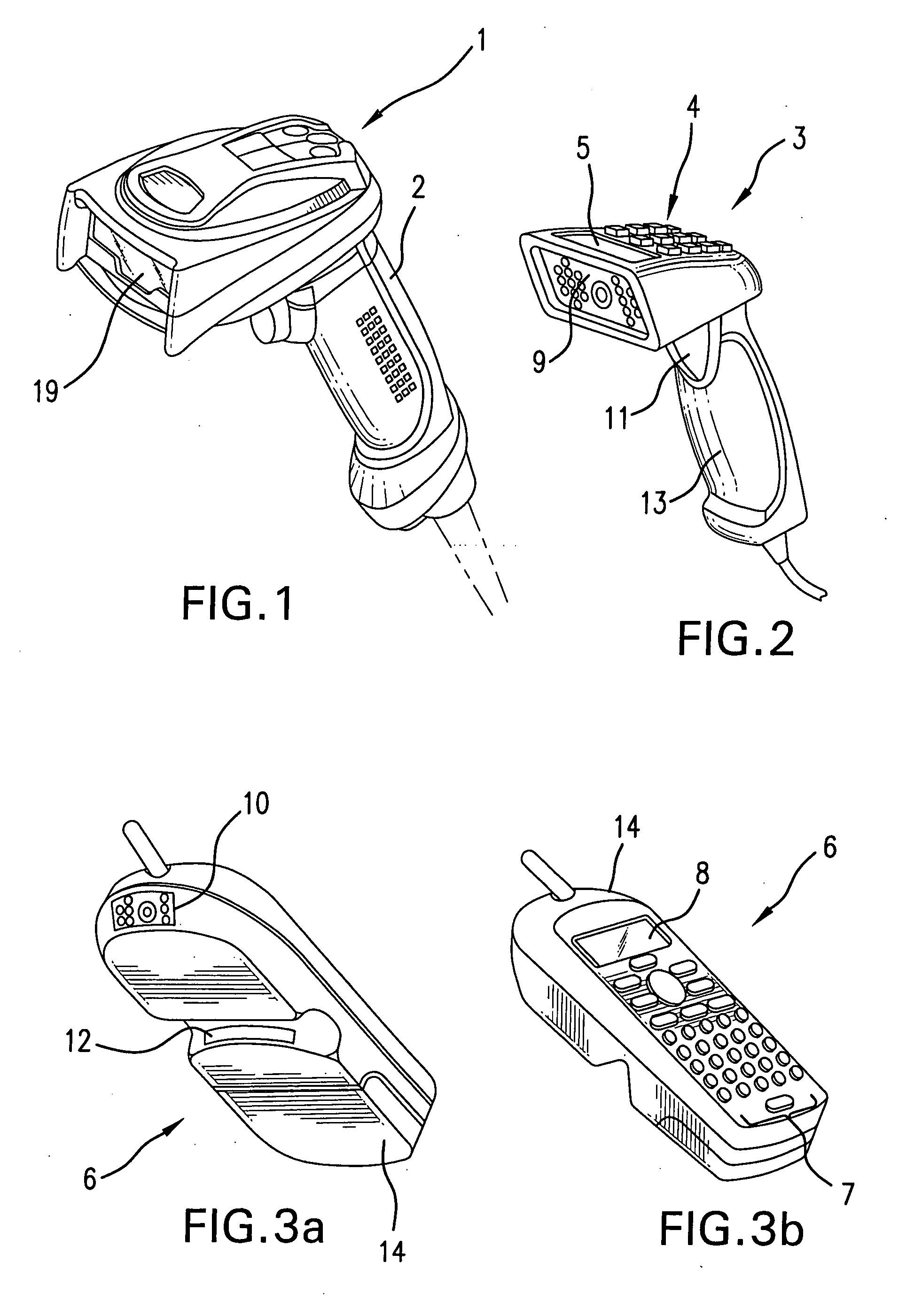
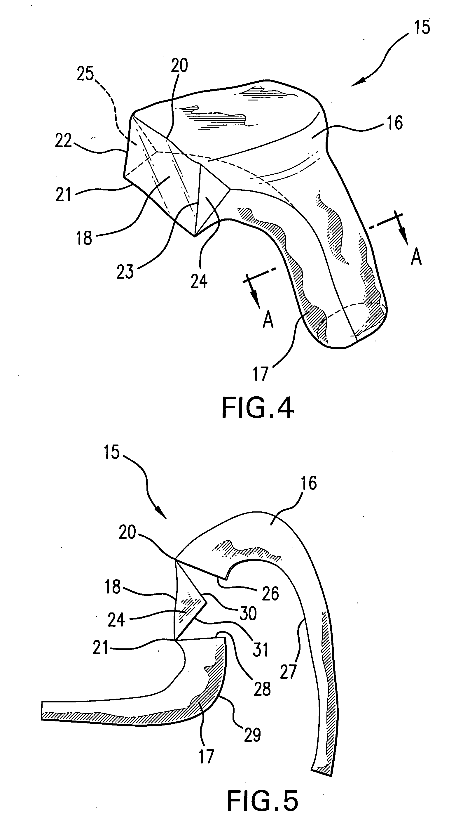
[0060]FIG. 4 illustrates an enclosure 15, in a closed configuration, according to the invention, for housing an imaging device of a type shown in FIGS. 1 and 2. In this embodiment, the enclosure can be made by thermoforming from an extruded thermoplastic sheet which, upon heating, can be drawn into a mold cavity by a vacuum, e.g., so that the heated sheet assumes the shape determined by the contours of the cavity. Thermoforming processes are well-known to those skilled in the art, which procedures can be adapted for manufacturing the subject enclosure and, therefore, further details of such processes, in general, are not herein described.

[0061]Suitable nonlimiting materials that can be used within the scope of the invention include ABS, polycarbonate, polystyrene, and PETG (polyethylene terephtalate glycol).

[0062]The one-piece enclosure of FIG. 4 can be considered a clam-shell, which includes a first part 16 and a second part 17, shown in FIG. 5 in an open configuration, which close...

second embodiment

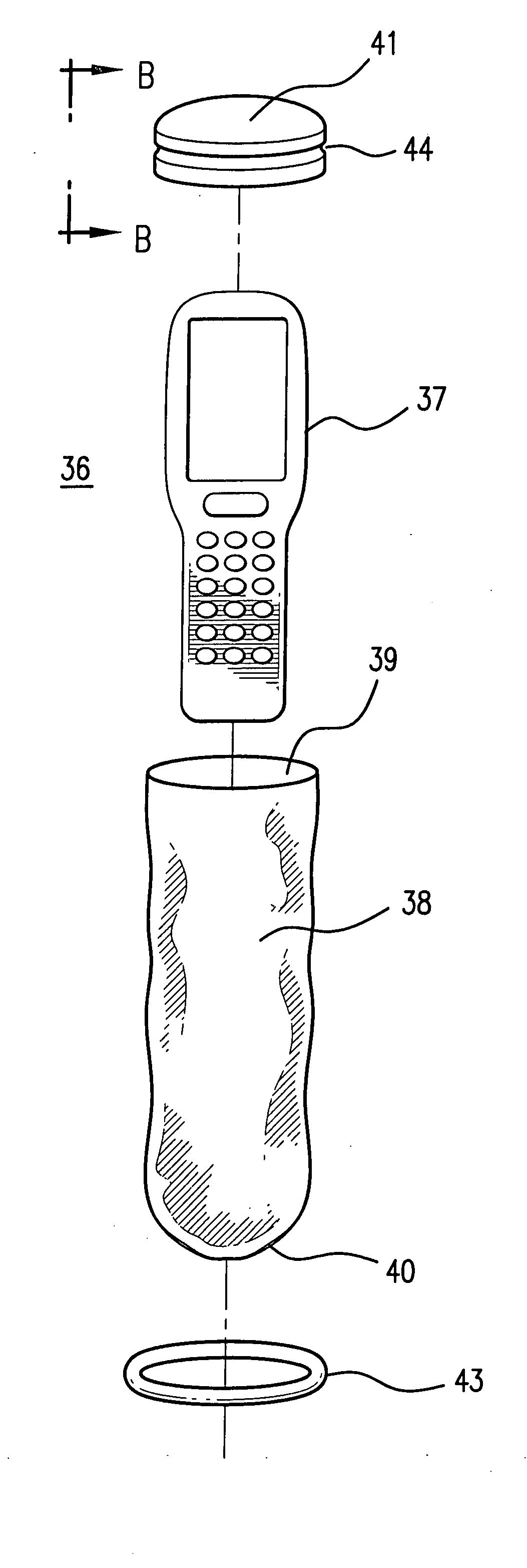
[0080]FIG. 10 illustrates an enclosure 36, in an open configuration, according to the invention, for housing an imaging device 37 of the PDT type. PDTs suitable for this enclosure include members of the 7900 or 9500 families of PDTs manufactured by Hand Held Products, Inc.

[0081]The enclosure of this embodiment comprises a number of parts, which can be considered to form a disposable kit for enclosing an imaging device. These parts include an outer bag 38, having an open upper end 39 and a closed lower end 40, as well as a hard plastic end cap 41.

[0082]Outer bag 38 can be a shapeless bag, such as a clear poly bag, and particularly can be a flexible shapeless bag. Alternatively, outer bag 38 can be rigid, in the manner of the enclosure of FIG. 4.

[0083]The end cap includes an integral molded-in window 42, which window can be formed as part of the manufacture of a two-shot thermoplastic end cap with an overmolded window, formed during an injection mold process. FIG. 11 shows that the wi...

third embodiment

[0089]In the embodiment of FIGS. 14 and 15, according to the invention, the shapeless bag 47 has an open lower end 48, rather than a closed end (such as the closed end of the bag 38 of the previous embodiment). The imaging device, such as the PDT of the previous embodiment, is inserted through the open end 48 and pushed up to mate with the end cap 49 (for which the O-ring groove could be omitted); this end cap is sealed to the bag 47, as mentioned above. After the imaging device is fully inserted into the bag 47, the open end 48 is then closed with a twist tie 50 or other sealing mechanism or suitable sealing expedient.

[0090]A variation of the third embodiment includes a longitudinal slit along the length of the bag, providing a longitudinal opening so that the imaging device can be more easily inserted into the bag. Such an embodiment would be advantageous in the event that the bag is more streamlined to the imaging device; this could be the case particularly if the embodiment were...


PUM


Abstract

An enclosure for housing a portable data transfer device, such as a bar code scanner, data collection device, or other equipment, for use in environments requiring a certain level of cleanliness, for protection against transmission of infection or merely dust or dirt, while allowing a full range of functional capability of such devices and equipment.

Description

BACKGROUND OF THE INVENTION[0001]1. Field of the Invention[0002]The invention relates to the field of imaging devices and data collection devices, particularly image and signal generated data collection devices, as well as to data transfer devices in general. More particularly, the invention is directed to protective enclosures for housing such devices during use, particularly for use in clean or sterile environments.[0003]2. Description of Background and Other Information[0004]Data collection devices, particularly bar code scanners and portable data terminals, are being used in an increasing variety of environments. In many of these environments, such as laboratories, hospitals, food processing areas, and so on, cleanliness and contamination of such devices can be of concern.[0005]For example, in the medical environment, such technology can be used for identification of equipment, patients, and medications, etc., so that, for instance, inventories can be monitored, medications can ...

Claims


Application Information

Patent Timeline
IPC IPC(8): B65D65/00
CPCG06K7/10881G06K2017/009H05K5/0086
Inventor HAVENS, WILLIAM H.HENNICK, ROBERT J.
Owner HAND HELD PRODS
Why Eureka
Try Eureka