Force Balanced Rotating Pressure Control Device

a control device and rotating pressure technology, applied in the direction of sealing, survey, borehole/well accessories, etc., can solve the problems of high probability of hydrocarbons being ignited, damage to equipment that maintains, and the possibility of blowout, so as to increase the service life of the bearings

Inactive Publication Date: 2008-12-04
SUNSTONE TECH
View PDF27 Cites 63 Cited by
  • Summary
  • Abstract
  • Description
  • Claims
  • Application Information

AI Technical Summary

Benefits of technology

[0008]A Rotating Pressure Control Device (RPCD) uses pressure balancing so that a force transmitted through the be

Problems solved by technology

When the hydrostatic weight of the column of mud in a well bore is less than the formation pressure, the potential for a blowout exists.
The pressure wave can damage the equipment that maintains the pressure within the well bore.
If the hydrocarbons reach the surface and exit the well bore through the damaged surface equipment, there is a high probability that the hydrocarbons will be ignited by the drilling or production equipment operating at the surface.
The ignition of the hydrocarbons produces an explosion and/or fire that is dangerous for the drilling operators.
The sealing element on all rotating pressure control heads eventually wear out because of friction caused by the rotation and/or reciprocation of the drill pipe.
Additionally, the passage of pipe joints, down hole tools, and drill bits through the rotating pressure control head causes the sealing element to expand an

Method used


Image

  • Force Balanced Rotating Pressure Control Device
  • Force Balanced Rotating Pressure Control Device
  • Force Balanced Rotating Pressure Control Device

Examples


Embodiment Construction

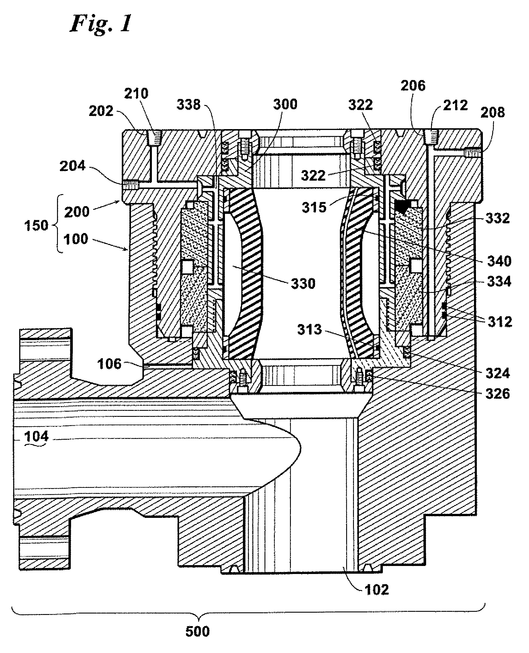
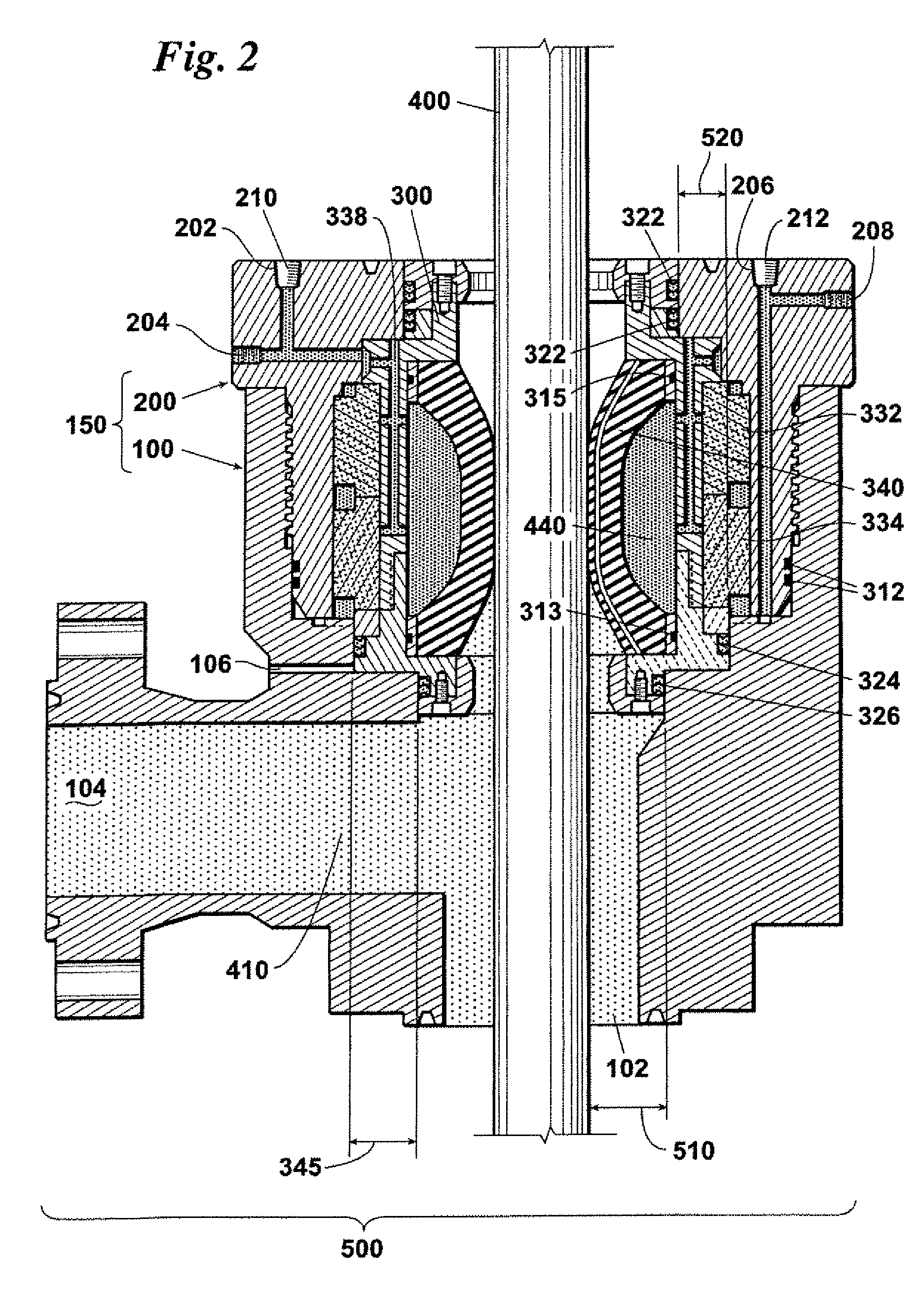
[0022]FIG. 1 is a cross sectional view of pressure balanced rotating pressure control device 500. Upper body 200 and lower body 100 form outer housing 150. Inner housing 300 rotates inside outer housing 150. Inner housing 300 contains sealing element 340 adapted to constrict around a drill pipe. Upper bearing 332 and lower bearing 334 affixed to inner housing 300 provide vertical and lateral support between inner housing 300 and outer housing 150.

[0023]Input port 204 allows hydraulic fluid to enter outer housing 150 to reach channel 338, cavity 330, and spaces between inner housing 300 and outer housing 150. Alternate input port 202 is capped with input plug 210. Output port 208 allows hydraulic fluid to exit outer housing 150. Alternate output port 206 is capped with output plug 212. Wellbore fluid enters RPCD at input 102 and exits through output 104.

[0024]Upper dynamic rotary seal 322 is located between inner housing 300 and outer housing 150 and above sealing element 340 and upp...


PUM


Abstract

Force balancing adjusts hydraulic fluid pressure in an upper piston area of a Rotating Pressure Control Device (RPCD) that has an inner housing rotatably engaged within an outer housing by an upper bearing and a lower bearing. The hydraulic fluid pressure is adjusted to balance net force in a upper piston area and a lower piston area. The fluid pressure adjustment creates a force differential that balances the total load transmitted through the upper bearing and the lower bearing and thereby extends the life of the sealing element and bearings. Additionally, a wear indicator signals the end of the useful life of the drill pipe sealing element.

Description

CROSS-REFERENCE TO RELATED APPLICATION[0001]The present invention is related to the subject matter of U.S. patent application Ser. No. 10 / 922,029.FIELD OF THE INVENTION[0002]The present invention is directed generally at drilling blowout preventers used in drilling oil and gas wells, and specifically to a rotating pressure control device for use in both under-balanced drilling applications and managed pressure drilling applications.BACKGROUND OF THE INVENTION[0003]When the hydrostatic weight of the column of mud in a well bore is less than the formation pressure, the potential for a blowout exists. A blowout occurs when the formation expels hydrocarbons into the well bore. The expulsion of hydrocarbons into the well bore dramatically increases the pressure within a section of the well bore. The increase in pressure sends a pressure wave up the well bore to the surface. The pressure wave can damage the equipment that maintains the pressure within the well bore. In addition to the pre...

Claims


Application Information

Patent Timeline
IPC IPC(8): E21B33/06E21B47/00
CPCE21B33/085E21B41/0021E21B47/01Y10S277/926
Inventor HUGHES, WILLIAM JAMESRICHARDSON, MURL RAYPETTIGREW, THOMAS L.VANDERVORT, KURT D.YOUNG, KENNETH D.
Owner SUNSTONE TECH
Why Eureka
Try Eureka