Electrically conductive buoyant cable

a technology of buoyant cables and conductive materials, applied in the direction of floating cables, insulated conductors, cables, etc., can solve the problems of cable reaching its maximum value, affecting the normal performance of cleaning devices, and affecting the service life of cables, so as to improve the buoyancy, increase flexibility, and increase the resistance to tensile stresses

Inactive Publication Date: 2008-12-04
SMARTPOOL
View PDF8 Cites 13 Cited by
  • Summary
  • Abstract
  • Description
  • Claims
  • Application Information

AI Technical Summary

Benefits of technology

[0046]It is an advantage of the electrically conductive buoyant cable of this invention to have better buoyancy, greater resistance to tensile stresses, increased flexibility a

Problems solved by technology

Remaining totally under water would hinder the normal performance of the cleaning device.
If a non-buoyant cable were used and rested at the bottom of the water, it would cause a great amount of tension to be exerted the cable.
In fact, such a cable could reach its maximum value and break.
Such breakage would cause the cable to cease to be able to perform its function.
Otherwise, the working area of the pool cleaning device will be greatly limited.
Also, the moving speed and moving direction of the device will be affected. FIG. 1 shows the analysis of the forces exerted on the electrically conductive buoyant cable during work During operation, the electrically conductive buoyant cable may be affected by torque, pressure and tension exerted by outside obstacles.
However, the hollow part of this kind of electrically conductive buoyant cable does not contain any components to withstand pressure.
This deformation leads to a decrease in the volume of the cable and thus causing the cable to lose buoyancy.
Using different materials increases the likelihood that there will be layer separation.
As a result, the electrically conductive buoyant cable will fold itself and irreversibly deform.
Furthermore, using a cable of this construction increases the likelihood that water will leak into the soft hollow tube damaging all or part of the cable.
Such leakage will consequently lead to loss of buoyancy of the entire cable.
So, there will likely be layer separation and the cable causing the cable to become irreversibly deformed after the tensioning force.
The use of foaming plastic or rubber material with air pockets to increase buoyancy typically lowers the tensile resistance the cable.
In these situations, the cable

Method used


Image

  • Electrically conductive buoyant cable
  • Electrically conductive buoyant cable
  • Electrically conductive buoyant cable

Examples


Embodiment Construction

[0056]To explain the objects and advantages of the swimming pool cleaning vehicle in accordance with the invention, the following description of the drawing and the exemplary embodiments are provided in detail. As will be appreciated by those skilled in the art the exemplary embodiments are provided to explain the swimming pool cleaning vehicle in accordance with the invention in detail and not to be used to limit its scope.

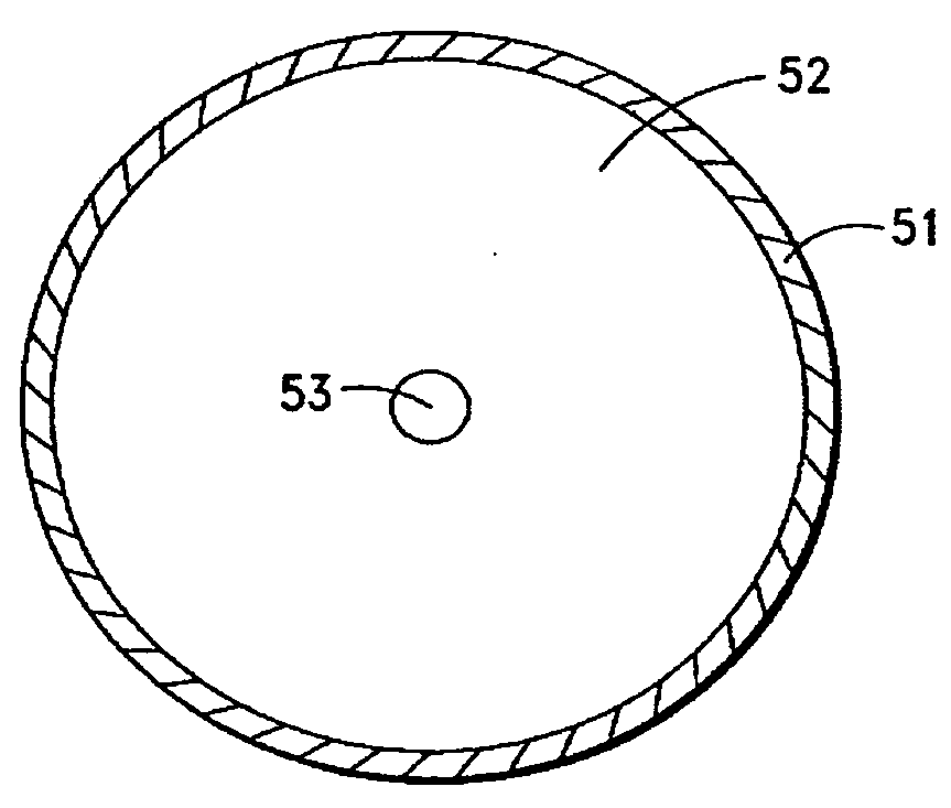
[0057]FIG. 5 shows a sectional view of one embodiment of the electrically conductive buoyant cable in accordance with this invention in one embodiment. The details are described below.

[0058]The electrically conductive buoyant cable in accordance with this invention includes a jacket (51) which is located along the same longitudinal axis as the cable generally, a filler layer (52) and at least one conductor (53). The filler layer surrounds and encloses the conductor (53). The jacket (51) surrounds the filler layer (52).

[0059]In an exemplary embodiment the preferre...


PUM


Abstract

Disclosed herein is an electrically conductive buoyant cable. The cable includes an electrical conductor member having at least one electrical conductor. The cable also includes a filler layer that consists of buoyant materials with relative density lower than 1. The filler layer surrounds and encloses the electrical conductor member. The invention includes a jacket, which, in one embodiment, contains a small quantity of filler material or no filler material. The jacket surrounds the filler layer. In one embodiment, the filler layer and the jacket are made of the same material.

Description

FIELD OF THE INVENTION[0001]This invention relates to an electrically conductive cable, in particular an electrically conductive buoyant cable.TECHNICAL BACKGROUND[0002]An electrically conductive buoyant cable is an electrical cable having a relative density below 1. The cable typically includes one or more conductors. Because the relative density of the electrically conductive buoyant cable is below 1, it will float on the surface of the water. In cases of interest in this application, the electrically conductive buoyant cable is connected to a mechanical device, which used for underwater applications, such as a pool cleaning device. The electrically conductive buoyant cable is used to provide an electrical power source to the pool cleaning device. Using the cable, it will be appreciated that a major part of the cable floats on the water. The remaining part of the cable runs between the cleaning device at the bottom of the water and the water surface.[0003]The above described elect...

Claims


Application Information

Patent Timeline
IPC IPC(8): H01B7/12
CPCH01B7/12
Inventor HUI, WING-KIN
Owner SMARTPOOL
Why Eureka
Try Eureka