Redundant Brake Actuators For Fail Safe Brake System

a brake actuator and redundancy technology, applied in the field of system control of the application of the brake, can solve the problems of high actuator force that has to be applied, large torque, and large amount of torque,

Inactive Publication Date: 2008-12-04
HALDEX BRAKE PROD AB
View PDF12 Cites 46 Cited by
  • Summary
  • Abstract
  • Description
  • Claims
  • Application Information

AI Technical Summary

Benefits of technology

[0017]Still another object of the present invention is to provide a system for controlling application of an electronically controlled brake having the above characteristics and which allows for a functioning portion of the brake actuator to provide at least a level of brake actuator control sufficient to avoid catastrophic consequences even during failure of another portion of the brake actuator.

Problems solved by technology

A major problem with conventional brakes with an electric actuator is the high actuator force that has to be applied in order to achieve a sufficient braking effect.
The necessary high actuator force and the resulting large power demand of the actuator make it necessary to employ very large drive units, usually electric motors, which have large torques, and are also heavy and expensive.
The result of this is that electromechanical brakes have, to date, not become widespread as vehicle brakes, for example.
For disc / pad friction coefficients larger than μinf, the self-enforced brake instead will become unstable, which means that a pulling force has to be applied to hold the brake at a specific brake force or else uncontrolled braking (i.e., lockup) can occur.
One of the ways in which failure can occur in such systems is if there is a failure within the control network that controls actuation of the brake actuators, or within the brake actuators themselves.
While the system disclosed in the '749 application does provide for some separation of control duties between the main control unit (80) and the auxiliary control unit (82), and does provide for some redundancy in certain respects, it does not provide true redundancy of brake actuation and suffers from serious disadvantages.
One of such disadvantages is that only the main control unit (80) is in direct communication with the central control unit (72) and with the various system sensors; the auxiliary control unit (82) communicates with these elements only through the main control unit (80).
Another disadvantage of the system described in the '749 application is that the auxiliary control unit (82) is capable of only very limited brake actuation, even when the auxiliary control unit (82) is fully functional.
As the '749 application itself recognizes, this provides only very limited control of the self-enforcing brake (10), permitting an open brake to remain open, and possibly permitting a closed brake to be caused to open.

Method used


Image

  • Redundant Brake Actuators For Fail Safe Brake System
  • Redundant Brake Actuators For Fail Safe Brake System
  • Redundant Brake Actuators For Fail Safe Brake System

Examples


Embodiment Construction

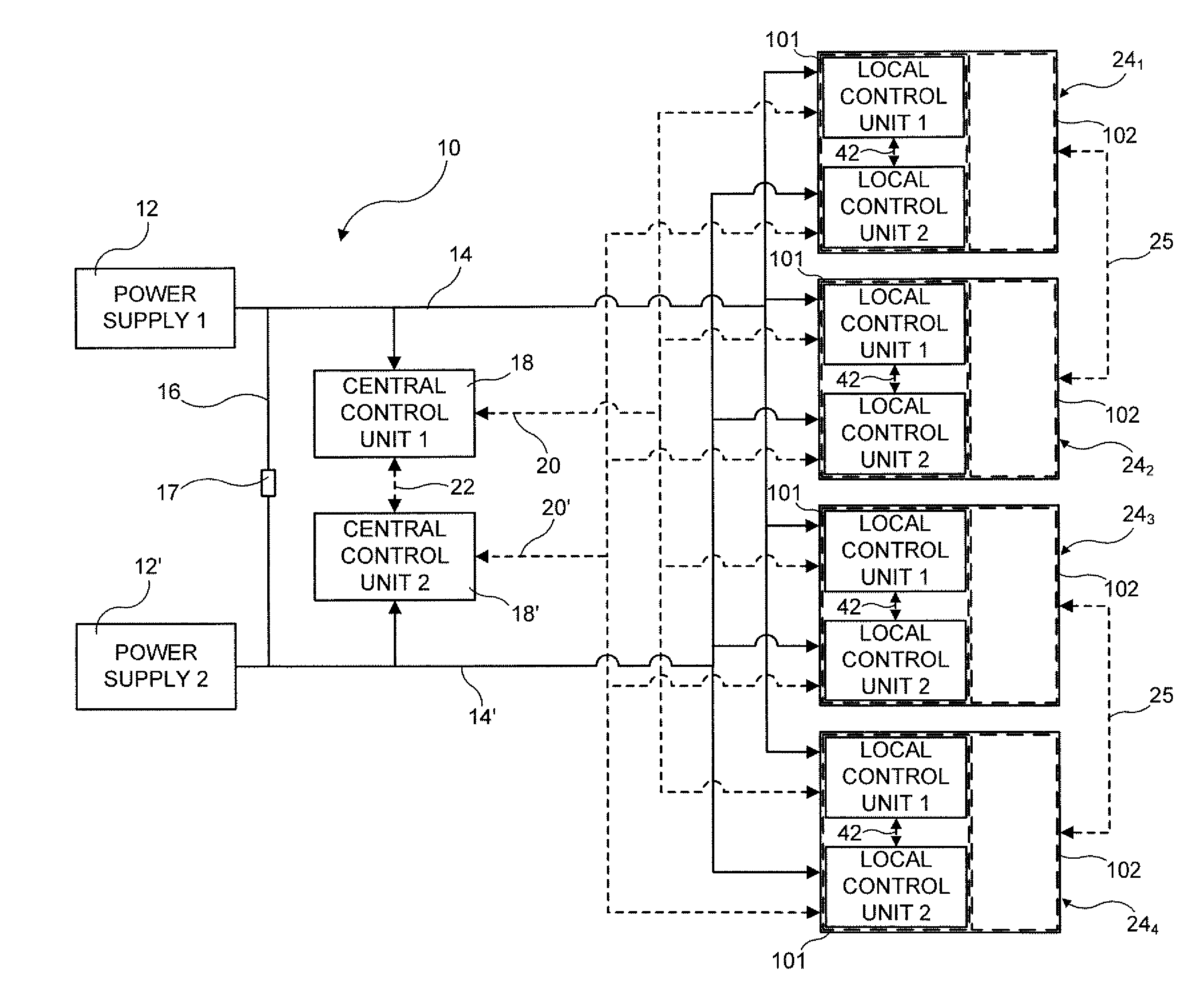
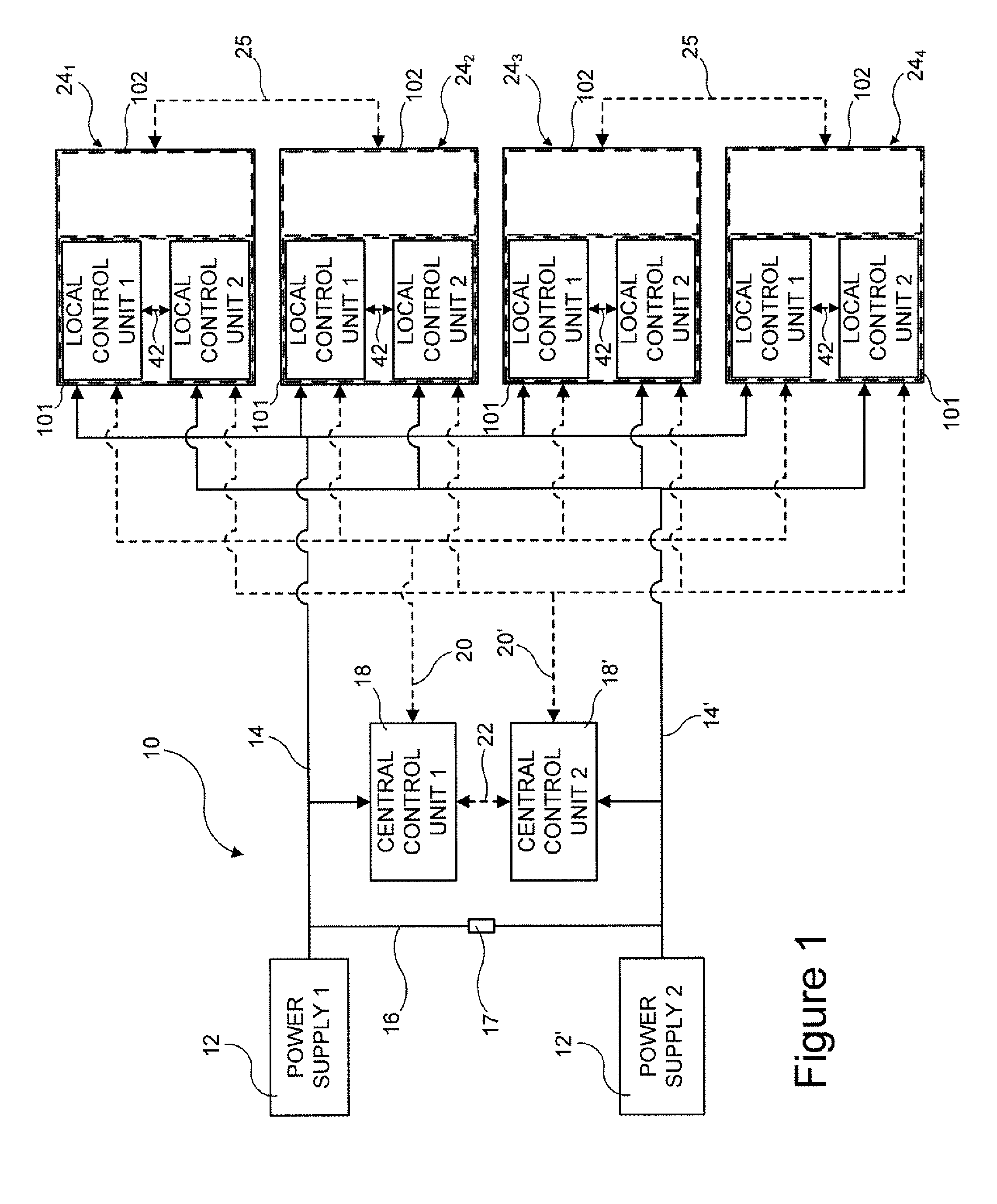
[0040]Referring first to FIG. 1, a vehicle brake system 10 in accordance with an exemplary embodiment of the present invention is shown. System 10 may be employed in any of numerous types of vehicles, although it should be noted that system 10 is particularly well-suited for use in heavy vehicles. It should also be noted that, in FIGS. 1-3 and 7, electrical power supply links are shown using solid lines, while communications links are shown using dashed lines.

[0041]System 10 includes at least a first power supply 12 supplying electrical power to a first power supply network 14 and a second power supply 12′ supplying electrical power to a second power supply network 14′. Preferably, although not necessarily, first and second power supply networks 14, 14′ are in communication via a link 16 so as to provide for power supply redundancy in first and second power supply networks 14, 14′ should one of first or second power supplies 12, 12′ fail. It is also preferable that an isolation mech...


PUM


Abstract

A vehicle brake system includes first and second central control units communicating with, respectively, first and second control networks, and a plurality of brake units. Each brake unit includes a brake component, a self-enforcing mechanism associated with and acting upon the brake component, and first and second actuation mechanisms acting upon the self enforcing mechanism, in response to, respectively, first and second actuation control signals, to cause actuation of the brake component. Each brake unit also includes first and second local control units in direct communication with, respectively, the first and second central control units via, respectively, the first and second control networks. The first and second local control units are in communication with, respectively, the first and second actuation mechanisms and transmit, respectively, the first and second actuation control signals to, respectively, the first and second actuation mechanisms, under certain circumstances, to cause actuation of the brake component.

Description

FIELD OF THE INVENTION [0001]The present invention relates generally to a system for controlling the application of a brake of a vehicle, which is particularly well-suited for controlling the application of an electromechanical brake with self-enforcing characteristics, and more specifically to a redundant brake actuator for use in connection with such a system to provide fail safe operation.BACKGROUND OF THE INVENTION [0002]Electromechanical brakes have been known for some time. U.S. Pat. No. 5,788,023 discloses a disc brake for a vehicle which can be actuated electrically and whose brake linings can be pressed against the brake disc with the aid of an electric motor. The electric motor transmits its actuation force, via a so-called planetary rolling-contact threaded spindle, onto an axially displaceably mounted piston which interacts with the brake lining.[0003]U.S. Pat. No. 5,829,557 discloses another vehicle disc brake which can be actuated electrically and whose brake linings c...

Claims


Application Information

Patent Timeline
Patent Type & Authority Applications(United States)
IPC IPC(8): F16D65/36G06F17/00G06G7/66F16D65/28
CPCB60T8/321B60T8/345B60T8/885B60T13/746B60T17/221B60T2270/404B60T2270/414B60T2270/82
Inventor NILSSON, PETER
Owner HALDEX BRAKE PROD AB
Why Eureka
Try Eureka