Shifting Device for Shifting a Motor Vehicle Gear Box
a technology for shifting devices and motor vehicles, applied in the direction of machines/engines, mechanical equipment, positive displacement engines, etc., can solve the problems of short shift time and small moving mass
- Summary
- Abstract
- Description
- Claims
- Application Information
AI Technical Summary
Benefits of technology
Problems solved by technology
Method used
Image
Examples
first embodiment
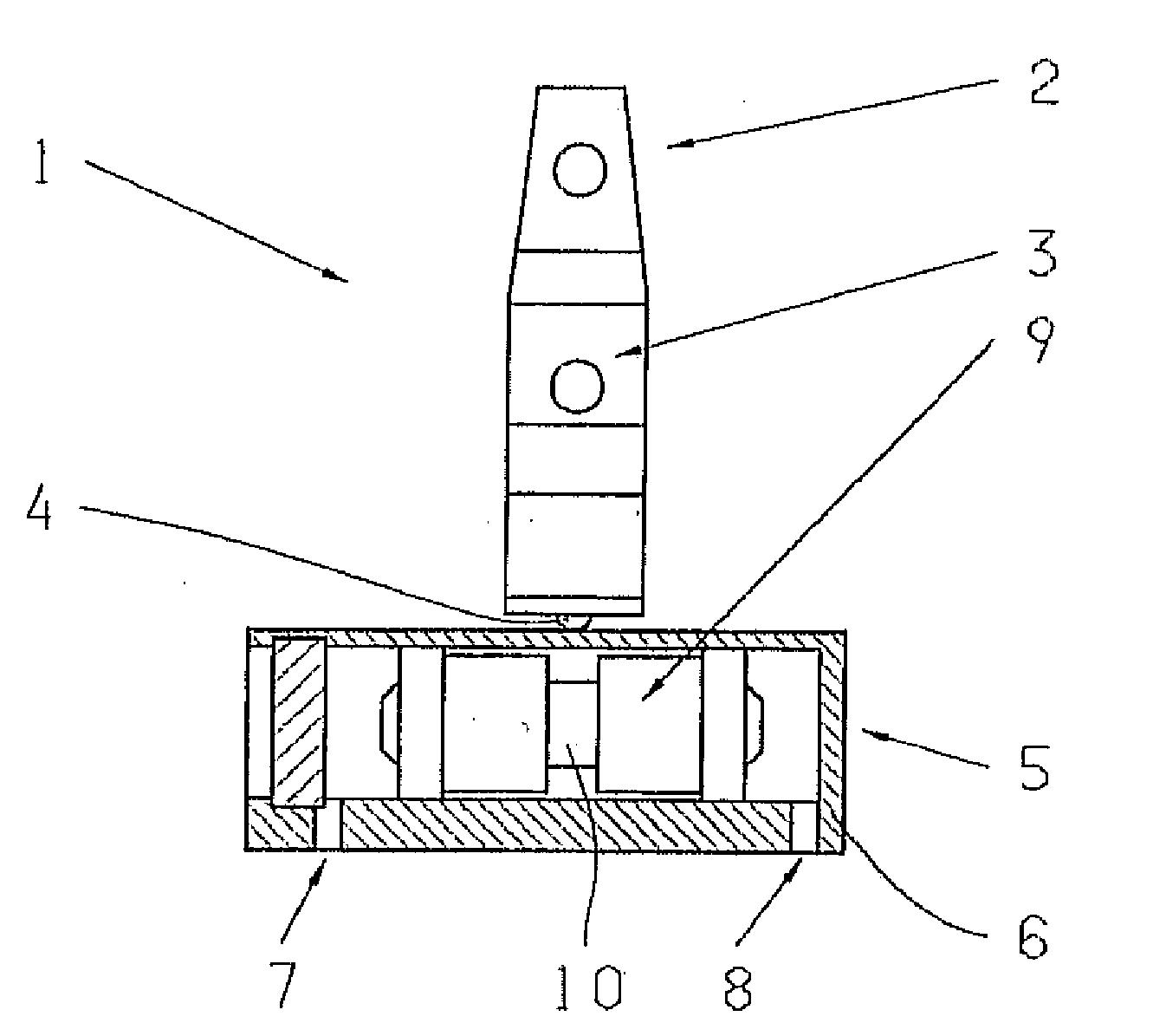
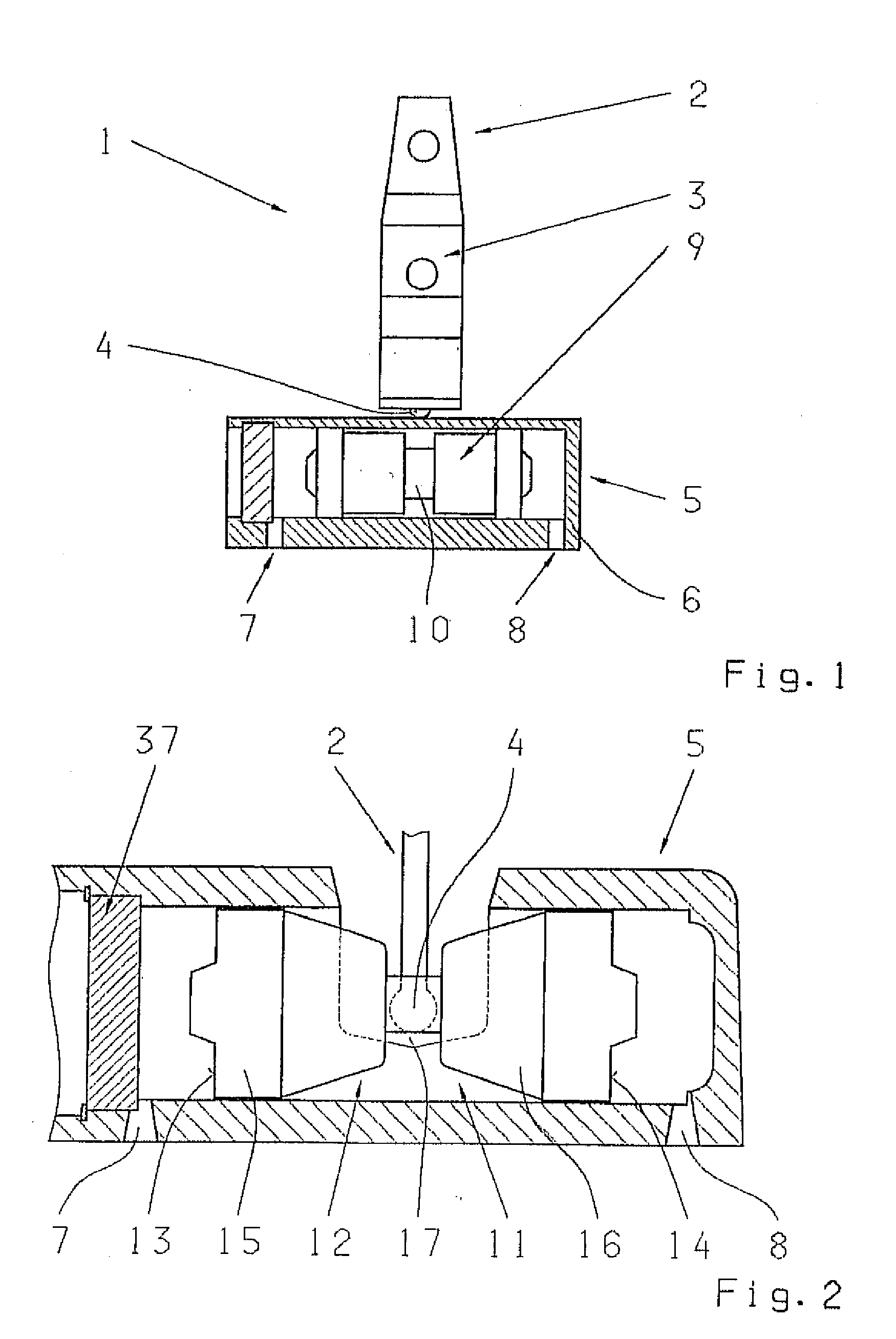
[0028]The shift cylinder 5 of the first embodiment, shown in FIGS. 1 and 2, is made as a horizontally acting, shift cylinder 11 that can be actuated from both sides which, as can be seen in FIG. 2, comprises a dual piston 12 whose piston faces 13, 14 can be acted upon by the fluid passed into the cylinder housing 6 through the pressure lines 7, 8. The dual piston 12 consists of two component pistons 15 and 16 connected to one another by a piston rod 17. The piston rod 17 is also connected in a detachable manner to the free end 4 of the shift element 2.
[0029]If fluid flows through line 7 and acts to exert pressure on the piston face 13 of the piston 15, the dual piston 12 is displaced to the right and the free end 4 of the shift element 2 as well is moved to the right. Depending on the mounting of the shift element 2, this will then undergo a lateral displacement or a tilting movement and, by virtue of known action upon coupling links, will bring about a corresponding shift operation...
second embodiment
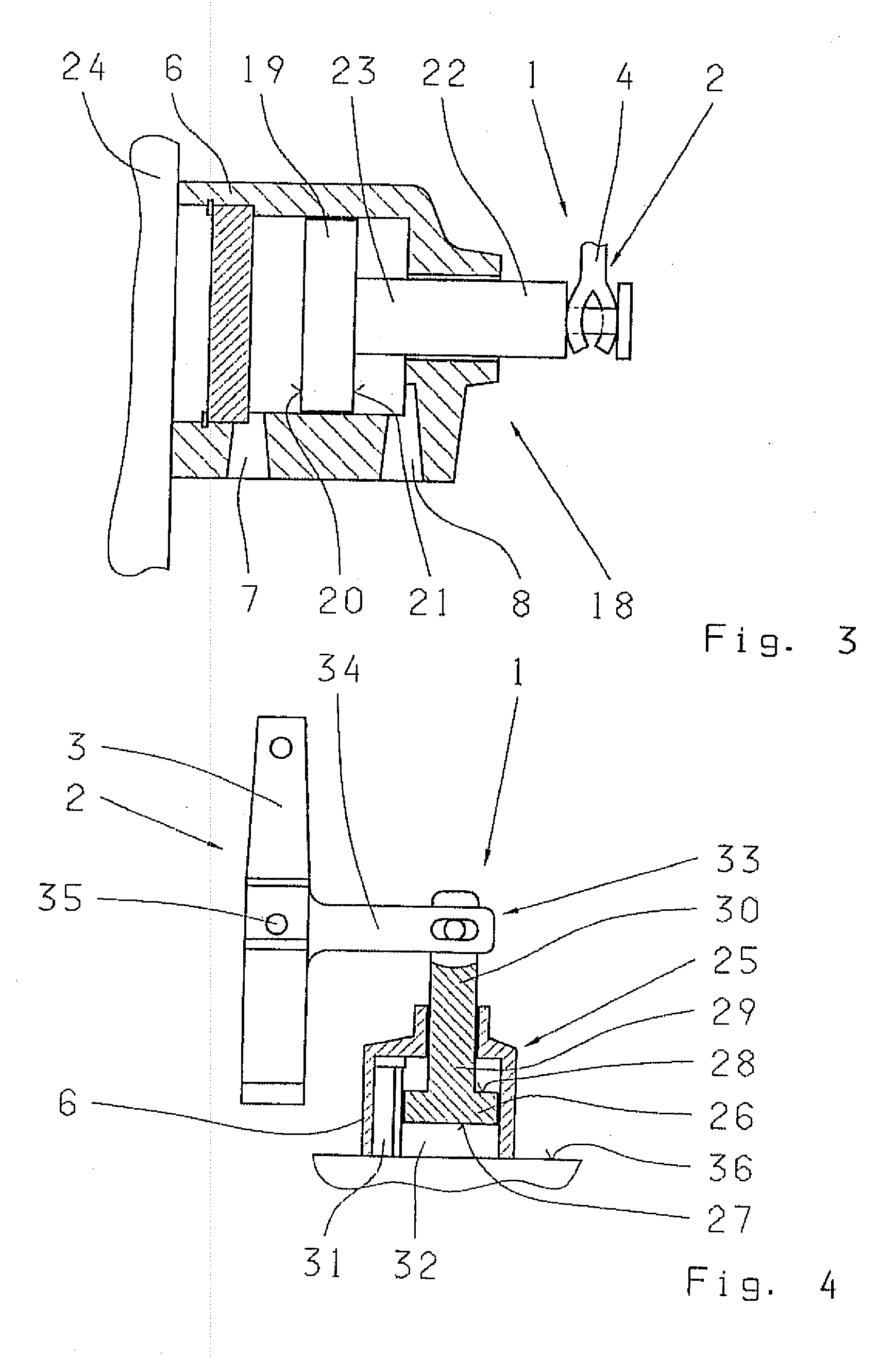
[0030]FIG. 3 shows shifting device 1 represented in longitudinal section. This shifting device 1 corresponds in principle to the shifting device 1 shown in FIG. 1, but the shift cylinder 5 is now made as a horizontally acting, stepped shift cylinder 18 that can be actuated from both sides. In contrast to the shift cylinder 11 in FIGS. 1 and 2, the shift cylinder 18 has only one piston 19, whose piston faces 20, 21 can be acted upon by the fluid and whose piston rod end 22 of a piston rod 23, located outside the cylinder housing 6, is connected to the free end 4 of the shift element 2.
[0031]The cylinder housing 6 of the shift cylinder 18 is, in addition, connected to a transmission housing wall 24 or to the housing of a hydraulic shift mechanism.
third embodiment
[0032]FIG. 4 shows the shift element 1 in which the shift cylinder 5 is this time made as a vertically acting, stepped shift cylinder 25 that can be actuated from both sides and which corresponds largely to the shift cylinder 18 shown in FIG. 2. Accordingly, the shift cylinder 25 has a piston 26 with two faces 27 and 28 and with a piston rod 29, whose piston rod end 30, located outside the cylinder housing 6, is connected to the free end 4 of the shift element 2. In contrast to the example embodiment shown in FIG. 2, the shift cylinder 25 has vertical pressure lines 31 and 32 through which fluid can flow into the shift cylinder 25 and act to exert pressure on the faces 27 and 28. The orientation of the cylinder housing 6, the piston rod 29 and the piston rod end 30 is also vertical.
[0033]The shift element 2, shown in FIG. 4 in the form of a shift rocker 3 has a free end 33 in the form of a web 34 extending at a right-angle from the shift rocker 3. The free end is connected to the pi...
PUM
 Abstract
Description
Claims
Application Information
 - R&D
- Intellectual Property
- Life Sciences
- Materials
- Tech Scout
- Unparalleled Data Quality
- Higher Quality Content
- 60% Fewer Hallucinations
Browse by: Latest US Patents, China's latest patents, Technical Efficacy Thesaurus, Application Domain, Technology Topic, Popular Technical Reports.
© 2025 PatSnap. All rights reserved.Legal|Privacy policy|Modern Slavery Act Transparency Statement|Sitemap|About US| Contact US: help@patsnap.com


