Spillway hydroelectric turbine

a technology of hydroelectric turbine and shaft, which is applied in the direction of electric generator control, renewable energy generation, greenhouse gas reduction, etc., can solve the problems of mechanical deterioration, lack of sufficient efficiency to economically produce hydroelectric power, and structures that do not provide enough adjustability, so as to achieve the effect of increasing the head pressur

Inactive Publication Date: 2008-12-04
LEDERER GARY +1
View PDF21 Cites 14 Cited by
  • Summary
  • Abstract
  • Description
  • Claims
  • Application Information

AI Technical Summary

Benefits of technology

[0008]This invention provides for a source of hydroelectric power which is able to be adjusted to increase head pressure, which is durable, and does not require large dams or large elevation changes.

Problems solved by technology

The sources of hydroelectric power involving water flowing through piping and water systems suffer from the drawback that large dams and large elevation changes are required for sufficient head pressure to produce hydroelectric power.
The sources involving known water wheels suffer from the drawback that they lack sufficient efficiency to economically produce hydroelectric power.
These structures do not provide enough adjustability and include parts which are subject to mechanical deterioration.

Method used


Image

  • Spillway hydroelectric turbine
  • Spillway hydroelectric turbine
  • Spillway hydroelectric turbine

Examples


Embodiment Construction

[0027]The present invention now will be described more fully hereinafter with reference to the accompanying drawing, in which a preferred embodiment of the invention is shown. This invention may, however, be embodied in many different forms and should not be construed as limited to the embodiments set forth herein; rather, these embodiments are provided so that this disclosure will be thorough and complete and will fully convey the scope of the invention to those skilled in the art.

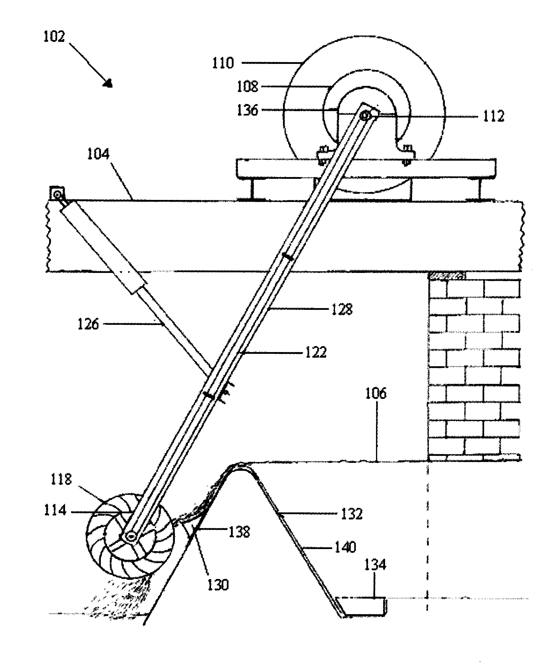
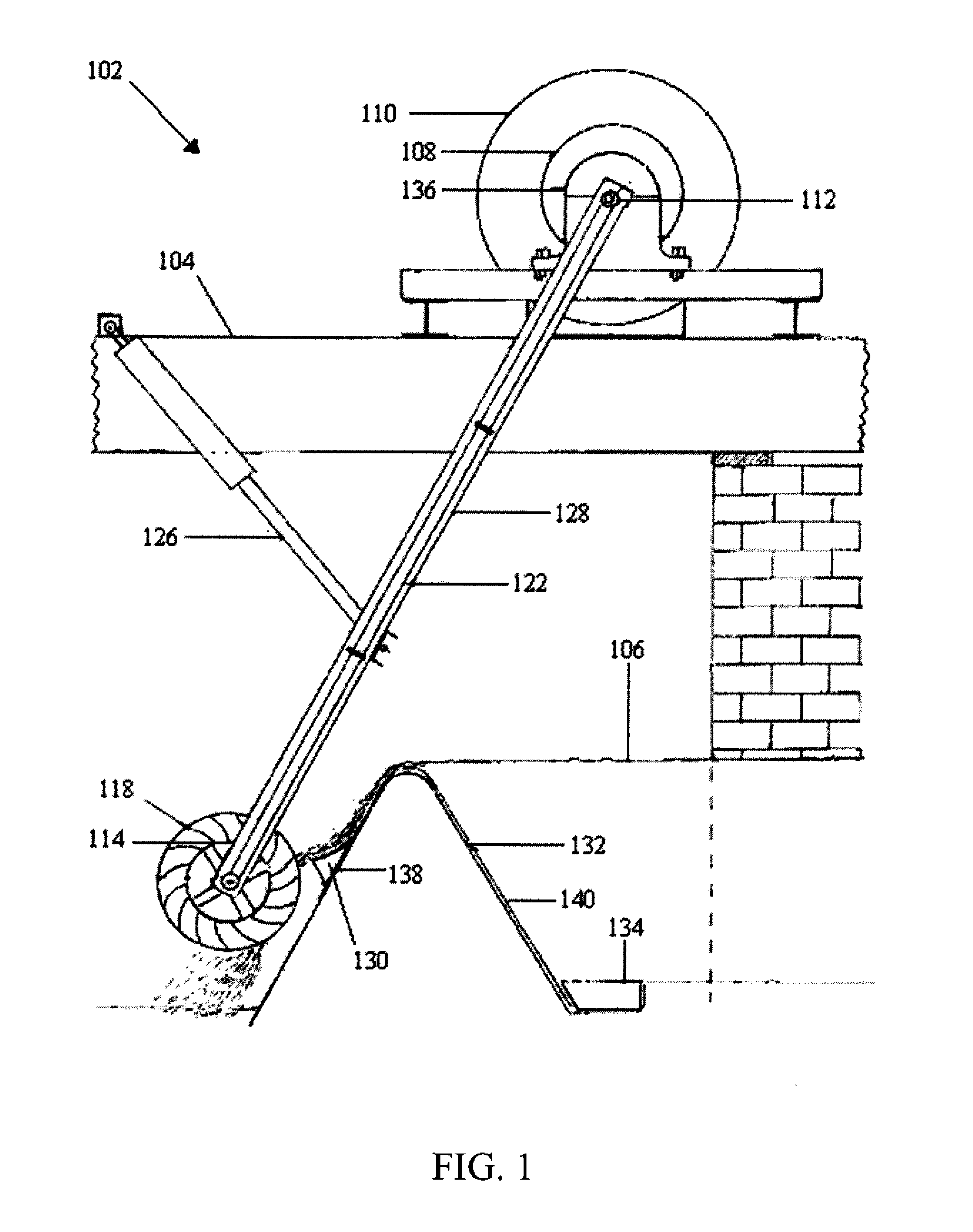
[0028]FIG. 1 illustrates a side view of an embodiment of the present invention wherein the hydroelectric system 102 includes a support member 104, a gear arrangement 108, a generator 110, a drive member 112, a support arm 128, and a retraction mechanism 126. In this embodiment, the support member 104 extends across a body of flowing water 106. In other embodiments, the support member does not extend across a body of flowing water but extends over an area of stagnant water or over land. In the embodiment i...


PUM


Abstract

A hydroelectric system comprising a support member, a rotational torque converter, a drive member being disposed at one end of a support arm, a water driven mechanism in rotational communication with the drive member, wherein the support arm can be pivotally adjusted by a retraction mechanism are disclosed. A spillway deflector comprising a spillway deflector wedge, a deflector anchor, and a flat portion extending between the deflector anchor and the deflector wedge are disclosed.

Description

CROSS REFERENCE TO RELATED PATENT APPLICATIONS[0001]This application claims the benefit of U.S. Provisional Application No. 60 / 932,022, filed May 29, 2007, which is hereby incorporated by reference in its entirety, and U.S. Provisional Application No. 61 / 070,956, filed Mar. 3, 2008, which is hereby incorporated by reference in its entirety.FIELD OF THE INVENTION[0002]The present invention is directed to a hydroelectric system and more particularly to a spillway hydroelectric system.BACKGROUND OF THE INVENTION[0003]Hydroelectric energy has been used for many years to produce electrical power. Many sources of hydroelectric power involve water flowing through piping and water systems which drive electrical generators. Other sources of hydroelectric power involve water wheels.[0004]The sources of hydroelectric power involving water flowing through piping and water systems suffer from the drawback that large dams and large elevation changes are required for sufficient head pressure to pr...

Claims


Application Information

Patent Timeline
Patent Type & Authority Applications(United States)
IPC IPC(8): F03B13/08
CPCF03B7/00F03B13/08F05B2250/41Y02E10/22Y02E10/223Y02E10/20
Inventor LEDERER, GARYLEDERER, ROSEANN
Owner LEDERER GARY
Why Eureka
Try Eureka