Dust removal and denitration equipment and method for transforming same

A technology for denitration transformation and equipment, applied in separation methods, chemical instruments and methods, and dispersed particle separation, etc., can solve problems such as reducing the denitration efficiency and life of SCR catalysts, reducing heat exchange efficiency, and SCR catalyst wear, and reducing equipment maintenance. Work and money, the effect of improving heat exchange efficiency and improving service life

Pending Publication Date: 2018-10-23
TIANJIN CEMENT IND DESIGN & RES INST +1
View PDF6 Cites 1 Cited by
  • Summary
  • Abstract
  • Description
  • Claims
  • Application Information

AI Technical Summary

Problems solved by technology

In order to save energy, the cement industry uses a multi-stage cyclone preheater for heat exchange and preheating of the raw meal powder. The dust removal efficiency is low, and the dust concentration at the outlet of the primary cylinder is relatively high.
High-concentration dust will quickly cause wear, alkali metal poisoning, and clogging of the SCR catalyst, which will greatly reduce the denitrification efficiency and life of the SCR catalyst. Therefore, high-temperature dust removal is required before SCR denitrification
However, the existing cement production process equipment is too much, the space is compact, and there is no extra space to place a high-temperature dust collector
At the same time, the high-c

Method used


Image

  • Dust removal and denitration equipment and method for transforming same
  • Dust removal and denitration equipment and method for transforming same
  • Dust removal and denitration equipment and method for transforming same

Examples


Embodiment Construction

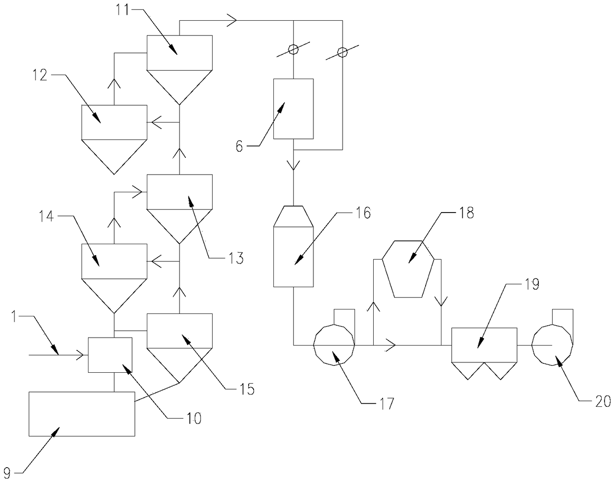
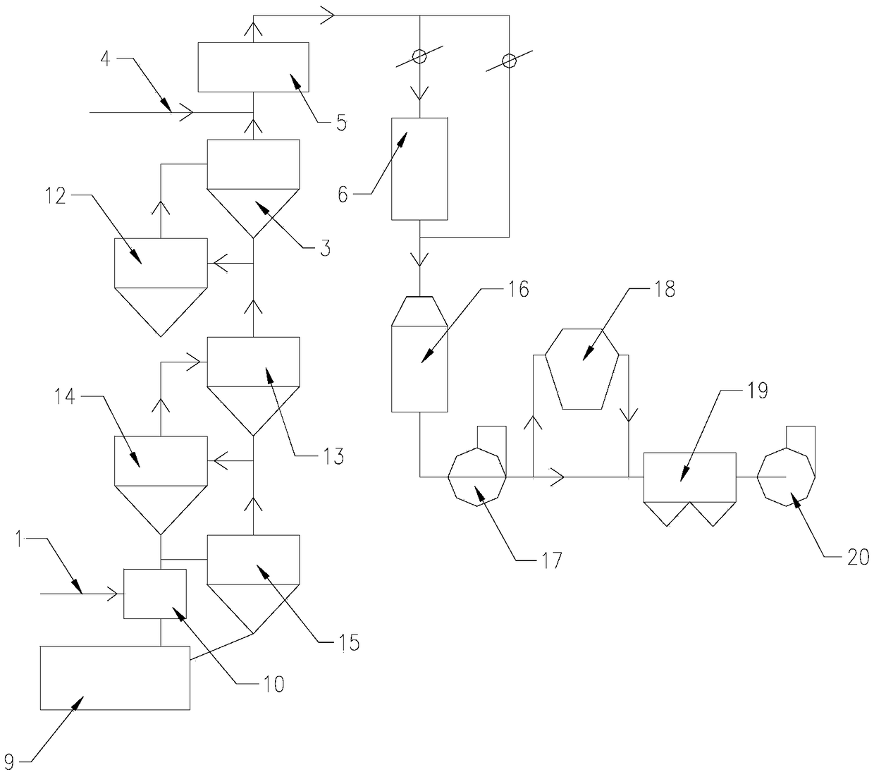
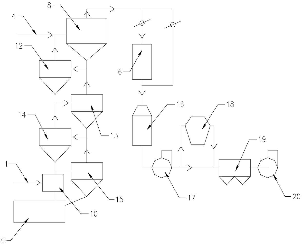
[0038] First of all, it should be noted that the specific structure, characteristics and advantages of the dust removal and denitrification equipment of the present invention and its transformation method will be explained in detail below by way of examples. However, all the descriptions are only for illustration and should not be used It is understood to form any limitation on the present invention. In addition, any single technical feature described or implied in each embodiment mentioned herein, or any single technical feature displayed or implied in each drawing, can still be used in these technical features (or their equivalents). ) Continue to perform any combination or deletion, so as to obtain more other embodiments of the present invention that may not be directly mentioned in this article. In addition, for the sake of simplification of the drawings, the same or similar technical features may only be labeled in one place in the same drawing.

[0039] It will be understo...


PUM


Abstract

The invention belongs to the field of dust removal and denitration, and particularly relates to dust removal and denitration equipment and a method for transforming the same. The dust removal and denitration equipment comprises a high-temperature dust remover, an ammonia spray system and an SCR (selective catalytic reduction) reactor. An outlet of the high-temperature dust remover is connected with an inlet of the SCR reactor, and the ammonia spray system is arranged at the front of the high-temperature dust remover or is arranged between the high-temperature dust remover and the SCR reactor.The dust removal and denitration equipment and the method for transforming the dust removal and denitration equipment have the advantages that the problems of vulnerability to abrasion, poisoning andblocking of SCR catalysts in high-concentration dust environments can be solved, the problems of abrasion of waste heat boilers and dust accumulation of pipe walls can be solved, the denitration efficiency can be improved, land occupation of the dust removal and denitration equipment can be economized, the heat exchange efficiency can be greatly improved, and the service lives of boilers can be greatly prolonged.

Description

Technical field [0001] The invention belongs to the field of dust removal and denitration, and particularly relates to a dust removal and denitration device and a modification method thereof. Background technique [0002] With the continuous improvement of national environmental protection standards, the existing denitrification technologies in the cement industry (including SNCR denitrification, low-nitrogen combustion, staged combustion, etc.) have low denitrification efficiency, generally around 60% to 80%, which can no longer meet higher NOx emissions Standard, it is necessary to adopt more efficient SCR denitration technology. Affected by the optimal reaction temperature of the SCR catalyst and ammonium bisulfate, the optimal position for SCR denitration is near the outlet of the preheater. In order to save energy, the cement industry uses a multi-stage cyclone preheater to preheat the raw meal powder. The dust removal efficiency is low, and the dust concentration at the ou...

Claims


Application Information

Patent Timeline
IPC IPC(8): B01D53/75B01D53/76B01D53/86B01D53/56
CPCB01D53/56B01D53/75B01D53/76B01D53/8625
Inventor 隋明洁王作杰张松彭学平陈昌华于浩波
Owner TIANJIN CEMENT IND DESIGN & RES INST
Why Eureka
Try Eureka