
System for capturing energy from a moving fluid

a fluid energy and fluid technology, applied in the field of energy conservation, can solve the problems of depletion of natural resources, energy overconsumption, inefficient energy consumption,

Inactive Publication Date: 2008-12-04
ELAHI NASIK
View PDF30 Cites 22 Cited by
  • Summary
  • Abstract
  • Description
  • Claims
  • Application Information

AI Technical Summary

Benefits of technology

[0014]It is accordingly an object of the invention to provide an energy recapture system that can be retrofitted to existing vehicles and carriers to provide means for recapturing energy, located on board the vehicle, and available on demand, without the need to purchase entirely new vehicles or carriers.
[0015]It is a further object of the invention to provide an energy recapture system that maximizes the amount of energy recaptured by the movement of a vehicle or carrier through a fluid, by maximizing the surface area of the carrier that is capable of recapturing energy from such movement.
[0017]It is a still further object of the invention to provide an energy recapture system that uses the relative movement of a fluid about a vehicle or carrier to provide electrical energy to separate a compound, such as water, into its constituent elements. One or both of the elements, for example, hydrogen and oxygen, may then be used as a significant fuel additive to complement the diesel fuel or gasoline in an internal combustion engine to run the engine more efficiently and cleanly.
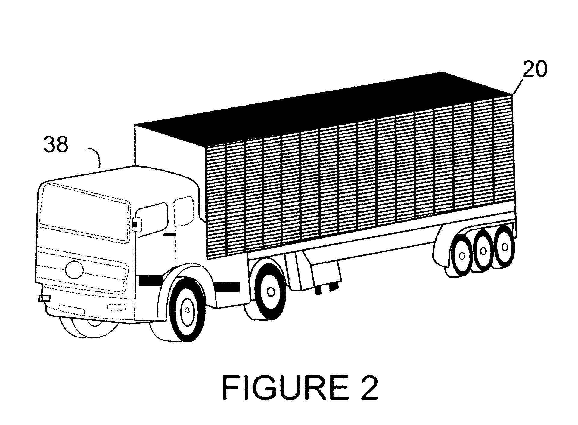
[0018]In accordance with these and other objects of the invention, briefly stated, there is provided an energy recapture system that may be retrofitted onto the surface of an existing object, such as a vehicle or carrier (the body of a truck, trailer, outer surface of containers used in shipping and trucking, the carriages of regular and freight trains and the like). To maximize the recapture, the wind pressure on the front of the moving vehicle is directed through channels which power multiple pods of variable energy producing turbines. Such a retrofitable system, in essence a mobile generating farm, includes means for removably attaching a plurality of energy generating modules or pods, such as wind driven turbines using magnetic or piezoelectric generators, to the exterior of the object, to help convert the kinetic energy of a fluid that moves about the object into another kind of energy that may be stored, such as chemical potential energy. When used to generate chemical potential energy, it is preferred that the kinetic energy of the moving fluid be used to electrolyze a compound such as water into its constituent elements. When this is done, at least one or both of these elements, hydrogen and oxygen, can be used directly or stored in the vehicle, for use on demand in an internal combustion engine associated with the object.

Problems solved by technology

The efficient use of energy is one of the most pressing issues facing the world today.
Inefficient energy consumption leads to energy overconsumption, which in turn leads to depletion of natural resources, global warming and a host of other difficulties.
For example, some automobile manufacturers have begun to sell cars that run exclusively on electricity but these vehicles have, thus far, seen a limited market.
Hybrid vehicles, and vehicles that use biodiesel or ethanol, however, are not the final word in the development of transportation alternatives relying upon more than the efficient use of the fuels that power the engines.
While the device taught therein may be useful in constructing some new devices, it is limited in its applicability in two significant areas.
First, the device taught therein cannot be applied to existing carriers.
That is, the referenced patent offers no guidance in how the device taught therein could be adapted for use with existing cars, trains and aircraft.
It would take a long time to retire all existing internal combustion engine vehicles, and, in developing regions with limited financial resources, there would be little incentive to dispose of an existing vehicle just to purchase or deploy a “greener” vehicle.
Second, the device taught in U.S. Pat. No. 6,740,988 is limited to generating a relatively small amount of electrical energy, while in certain applications greater and other forms of energy would be useful.
It teaches, however, that using fuel cells to power the vehicle is “not practical”, and further teaches placement of the turbines on the roof of the vehicle, limiting its applicability to electric vehicles.

Method used


Image

  • System for capturing energy from a moving fluid
  • System for capturing energy from a moving fluid
  • System for capturing energy from a moving fluid

Examples


Embodiment Construction

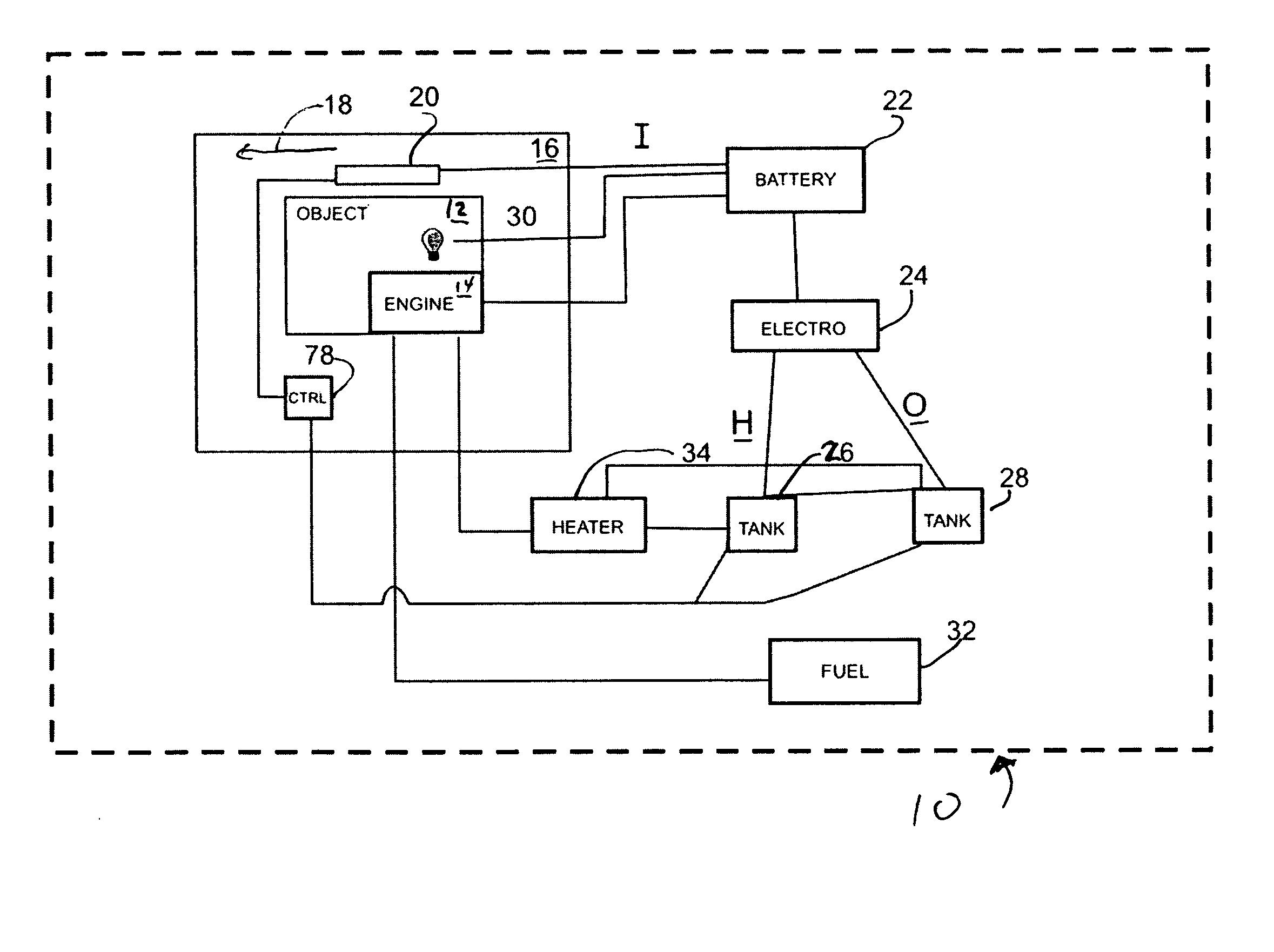
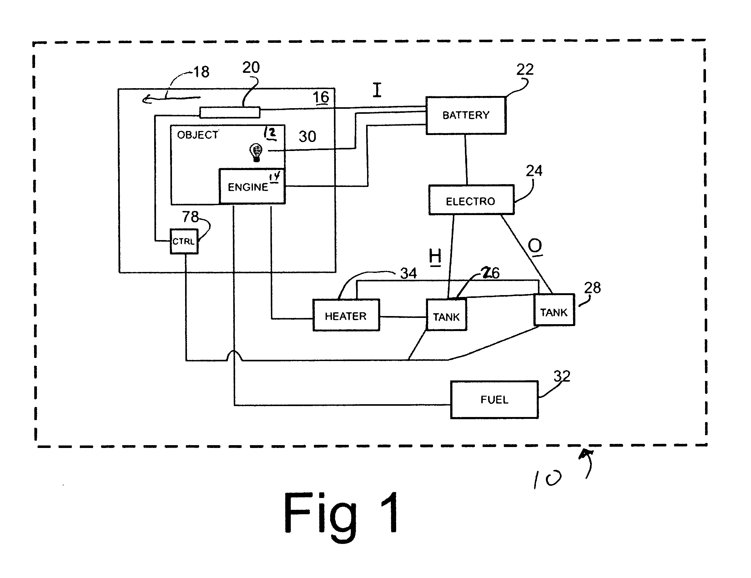
[0041]FIG. 1 shows, generally at 10, a schematic diagram of the inventive energy recapture system for use with an object 12, such as a vehicle, e.g., an automobile, a truck, an airplane, a boat or other type of air- or watercraft, or a carrier, e.g., a container carried on a flatbed truck, a non-engine car of a train or other object that is carried, or otherwise moved, by a vehicle. Preferably, object 12 is associated with an engine 14, which is preferably a combustion engine, a hybrid engine or a hydrogen-fuel cell engine, and which is most preferably an internal combustion engine. If object 12 is a vehicle, then engine 14 may be the engine that moves the vehicle. If object 12 is a carrier, then engine 14 may be part of the vehicle that moves the carrier.

[0042]Object 12 is disposed within a fluid 16, and there exists relative movement (represented diagrammatically by arrow 18) between object 12 and fluid 16. Object 12, for example, may be moving through fluid 16, as a truck through...


PUM


Abstract

An energy recapture system that may be retrofitted to an existing object, such as a vehicle or carrier. The retrofitable system includes means for removably attaching a plurality of wind or fluid driven energy generating modules, such as magnetic or piezoelectric generators, to the exterior of the object, to convert the kinetic energy of a fluid that moves about the object into another kind of energy that may be stored, such as electrical or chemical potential energy. When used to generate chemical potential energy, it is preferred that the kinetic energy of the moving fluid be used to electrolyze a compound such as water into its constituent elements; at least one of these elements, hydrogen and / or oxygen, can be stored for later use in an internal combustion engine associated with the object.

Description

RELATED APPLICATIONS[0001]This application is a continuation-in-part of my earlier-filed provisional application Ser. No. 60 / 932,159, filed May 29, 2007, the priority of which is hereby claimed.BACKGROUND OF THE INVENTION[0002]1. Field of the Invention[0003]The invention is directed to the field of energy conservation and, more particularly, to devices and systems for capturing kinetic energy from the relative movement of a fluid and an object, and for converting that kinetic energy into another form of energy.[0004]2. Description of the Related Art[0005]The efficient use of energy is one of the most pressing issues facing the world today. Inefficient energy consumption leads to energy overconsumption, which in turn leads to depletion of natural resources, global warming and a host of other difficulties. Still, there is no end in sight for the demand for energy. While many industrialized nations seek to combat energy overconsumption by limiting the use of non-renewable energy source...

Claims


Application Information

Patent Timeline
IPC IPC(8): F03D9/00B60K6/00F03B13/00
CPCB60K16/00B60K2016/006F03D9/002F03D11/04F05B2220/61F05B2240/40F05B2240/921F05B2240/931F05B2240/941Y02E10/727Y02E70/10Y02T10/90Y02E10/725F03D13/20F03D9/25Y02E10/72Y02E60/36F03D1/04F03D1/02F03D9/32
Inventor ELAHI, NASIK
Owner ELAHI NASIK
Learn More