Magnetic field coil and magnetic resonance imaging apparatus

a magnetic field coil and magnetic resonance imaging technology, applied in the field of magnetic field coils, can solve the problems of insufficient sensitivity and limited region providing favorable sensitivities for both kinds of signals, and achieve high sensitivity, uniform sensitivity, and high sensitivity.

Inactive Publication Date: 2008-12-04
HITACHI LTD
View PDF6 Cites 15 Cited by
  • Summary
  • Abstract
  • Description
  • Claims
  • Application Information

AI Technical Summary

Benefits of technology

[0011]According to the present invention, in an MRI apparatus, the RF coil can highly efficiently and uniformly irradiate a RF magnetic field having two or more magnetic resonance frequencies close to each other, and receive magnetic resonance signals of these frequencies with high sensitivity and uniform sensitivity profile.

Problems solved by technology

Since sensitivity profiles of the double-tuned saddle-type RF coils and double-tuned birdcage RF coils corresponding to two kinds of magnetic resonance signals significantly differ from each other, the region providing favorable sensitivities for both kinds of the signals is limited.
Moreover, the QD (quadrature detection) system which improves the sensitivity 1.4 times cannot be employed in these double-tuned RF coils, and therefore sufficient sensitivity cannot be obtained.

Method used


Image

  • Magnetic field coil and magnetic resonance imaging apparatus
  • Magnetic field coil and magnetic resonance imaging apparatus
  • Magnetic field coil and magnetic resonance imaging apparatus

Examples


first embodiment

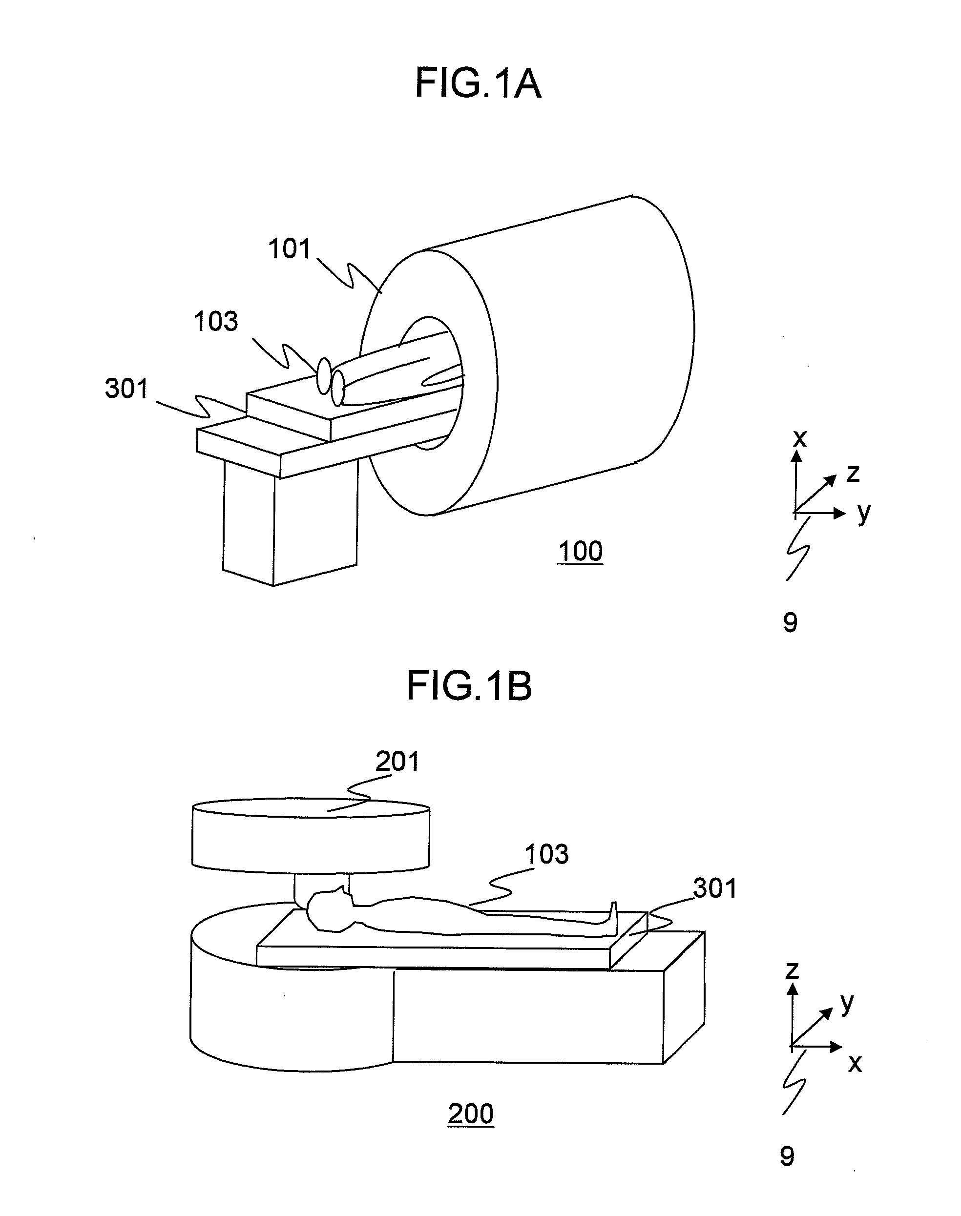
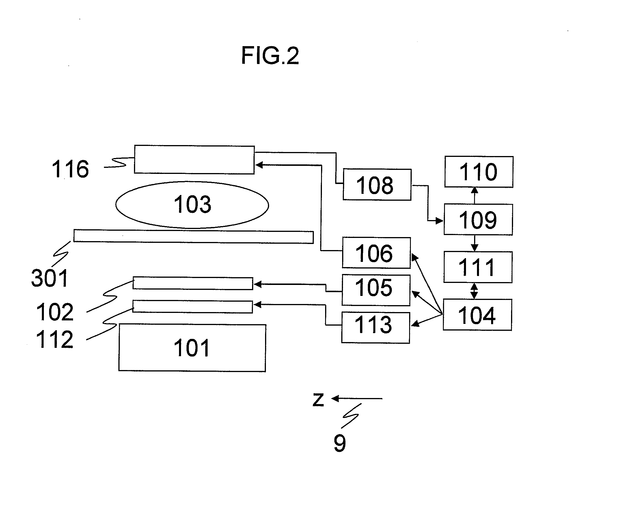
[0033]The first embodiment of the RF coil according to the present invention will be explained. The whole configuration of an MRI apparatus having the RF coil of this embodiment will be explained first. FIG. 1A and FIG. 1B are schematic views of the MRI apparatus having the RF coil of this embodiment. In the diagrams, the direction of the z axis in the coordinate 9 is a static magnetic field direction. The MRI apparatus 100 shown in FIG. 1A is provided with a horizontal magnetic field type magnet 101. The MRI apparatus 200 shown in FIG. 1B is provided with a vertical magnetic field type magnet 201. These MRI apparatuses 100 and 200 are provided with a table 301 on which a subject 103 is placed. This embodiment is applicable to both the MRI apparatus 100 provided with the horizontal magnetic field type magnet 101, and the MRI apparatus 200 provided with the vertical magnetic field type magnet 201. Hereafter, the present invention will be explained for the MRI apparatus 100 having the...

second embodiment

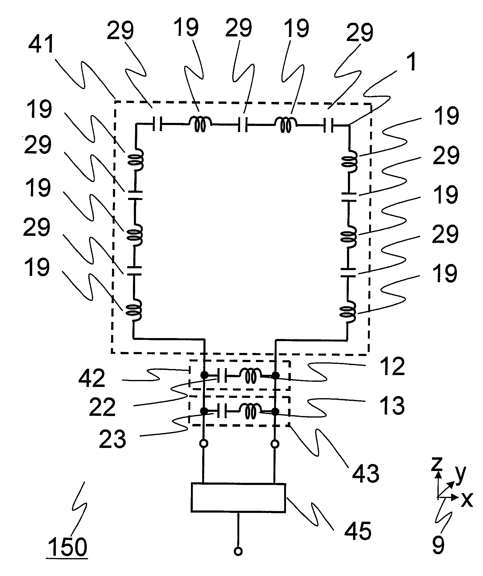
[0092]Hereafter, the second embodiment of the present invention will be explained. The configuration of the MRI apparatus based on this embodiment is basically the same as that of the first embodiment. In this embodiment, as the transmit and receive RF coil 116, a combination of two of double-tuned loop-type coils 150 of the first embodiment is used to realize the quadrature detection (QD) for improving irradiation efficiency and reception sensitivity of the transmit and receive RF coil. The configuration of this embodiment different from that of the first embodiment will be explained below.

[0093]FIG. 12A and FIG. 12B are diagrams for explaining the transmit and receive RF coil 116 of this embodiment, and FIG. 12A is a circuit diagram of the transmit and receive RF coil 116. In the diagram, the direction of the z axis in the coordinate 9 is the static magnetic field direction. As shown in this diagram, the transmit and receive RF coil 116 of this embodiment is provided with a first ...

third embodiment

[0101]Hereafter, the third embodiment of the present invention will be explained. The configuration of the MRI apparatus of this embodiment is basically the same as that of the first embodiment. In this embodiment, a transmit RF coil 116a and a receive RF coil 116b are independently provided instead of the transmit and receive RF coil 116 of the first embodiment. Here, explanation will be made by exemplifying a case where a double-tuned birdcage RF coil having a birdcage shape is used as the transmit RF coil 116a, and a double-tuned loop-type coil having a loop coil shape is used for the receive RF coil 116b. Hereafter, the embodiment will be explained by emphasizing the configuration different from that of the first embodiment.

[0102]FIG. 14 is a block diagram for explaining connection of the RF coil of this embodiment, a RF magnetic field generator 106 and a receiver 108. As shown in this diagram, the RF coil of this embodiment is provided with a double-tuned birdcage RF coil 70, w...


PUM


Abstract

Provided is an RF coil which can highly efficiently and uniformly irradiate a RF magnetic field having two or more magnetic resonance frequencies close to each other, and receive magnetic resonance signals of two or more magnetic resonance frequencies close to each other with high sensitivity and uniform sensitivity profile in an MRI apparatus. Two or more frequencies to which the coil is tuned are adjusted so as to be between resonance frequencies of series resonant circuits constituting the RF coil.

Description

CLAIM OF PRIORITY[0001]The present application claims priority from Japanese application JP 2007-145029 filed on May 31, 2007, the content of which is hereby incorporated by reference into this application.BACKGROUND OF THE INVENTION[0002]The present invention relates to a magnetic resonance imaging (MRI) apparatus, and more particularly to a RF (radio-frequency) coil for detecting nuclear magnetic resonance images of two or more kinds of nuclides.[0003]MRI apparatuses are diagnostic imaging apparatuses for medical use, which induce magnetic resonance of atomic nuclei in arbitrary sections crossing a subject and obtain tomograms of the sections from generated magnetic resonance signals. As the magnetic resonance signals, those of hydrogen nuclei (1H) are generally used.[0004]MRS (magnetic resonance spectroscopy) and MRSI (magnetic resonance spectroscopic imaging), which are types of magnetic resonance imaging methods, are used as methods for measuring metabolic conditions in the liv...

Claims


Application Information

Patent Timeline
Patent Type & Authority Applications(United States)
IPC IPC(8): G01R33/34
CPCG01R33/34046G01R33/34053G01R33/34069G01R33/34076G01R33/341G01R33/3635
Inventor OTAKE, YOSUKESOUTOME, YOSHIHISAHIRATA, KOJIBITO, YOSHITAKA
Owner HITACHI LTD
Why Eureka
Try Eureka