Head mounted display and control method therefor

Active Publication Date: 2008-12-04
CANON KK
View PDF1 Cites 103 Cited by
  • Summary
  • Abstract
  • Description
  • Claims
  • Application Information

AI Technical Summary

Benefits of technology

[0011]The present invention has been made in consideration of the above problems, and has as its object to provide a technique for, when a virtual space image and a physical space image are comp

Problems solved by technology

However, the following problems arise in a method of compositing a physical space image and a CG image generated based on viewpoint information at the time of sensing the physical space image, and displaying the composited image.
This causes a delay in displaying the composite image after the physical space image is sensed, as a matter of course.
In particular, when the viewpoint moves quickly, the delay is conspicuous.
In a method of creating a CG image in advance b

Method used


Image

  • Head mounted display and control method therefor
  • Head mounted display and control method therefor
  • Head mounted display and control method therefor

Examples


first embodiment

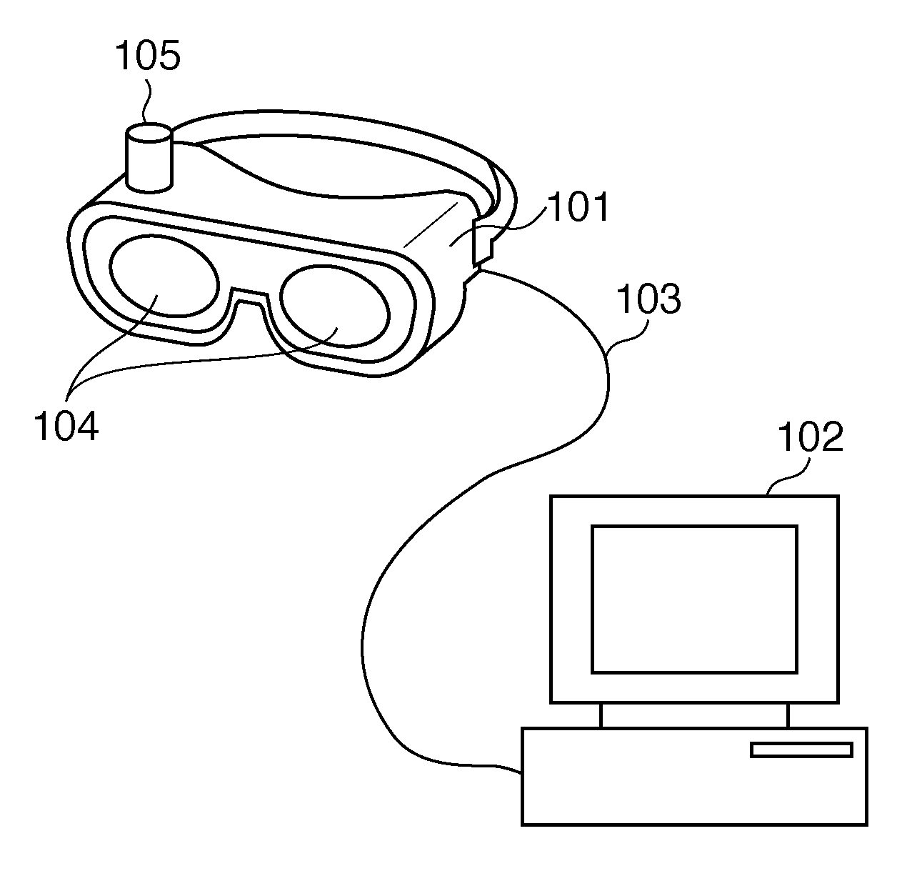
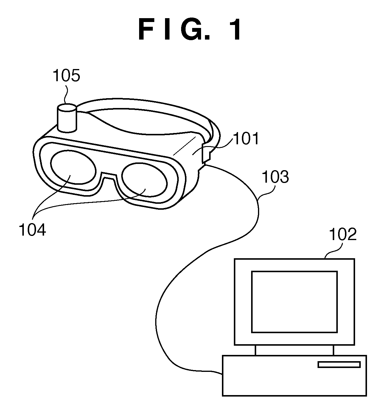
[0037]FIG. 1 is a view showing the outer appearance of a system to which a head mounted display (HMD) according to this embodiment is applied. As shown in FIG. 1, the system according to this embodiment comprises an HMD 101 and a PC (Personal Computer) 102. The HMD 101 and the PC 102 are connected with each other via a cable 103. The connection method between the HMD 101 and the PC 102 is not limited to this, and either a wired or wireless connection method may be used.

[0038]The HMD 101 will be described first. As is well known, the HMD 101 is worn by an observer on the head.

[0039]Reference numeral 105 denotes a position and orientation sensor which measures the position and orientation of itself. As this position and orientation sensor 105, various sensors such as an optical sensor, mechanical sensor, and ultrasonic sensor are applicable. In this embodiment, a magnetic sensor is used as the position and orientation sensor 105. In this case, the position and orientation sensor 105 o...

second embodiment

[0103]In this embodiment, a CG image and physical space image both of which have been shifted are composited. That is, a process corresponding to a flowchart obtained by modifying the flowchart of FIG. 9 by omitting step S909 and changing the flowchart so as to execute both steps S910 and S911, is performed. Furthermore, a shift Δθ used to calculate a shift amount used in step S910 is different from a shift Δθ used to calculate a shift amount used in step S911.

[0104]The shift Δθ for step S910 represents the remainder (difference amount) obtained by subtracting the orientation component in the horizontal direction of the orientation components represented by the first position and orientation information from the orientation component in the horizontal direction of the orientation components represented by the reference position and orientation information. That is, the shift Δθ for step S910 represents the first difference value.

[0105]The shift Δθ for step S911 represents the remain...

third embodiment

[0106]The outer appearance of a system to which an HMD according to this embodiment is applied is similar to that in the first embodiment, and thus the outer appearance shown in FIG. 1 will be used. In this embodiment, the different points from the first embodiment will be described below.

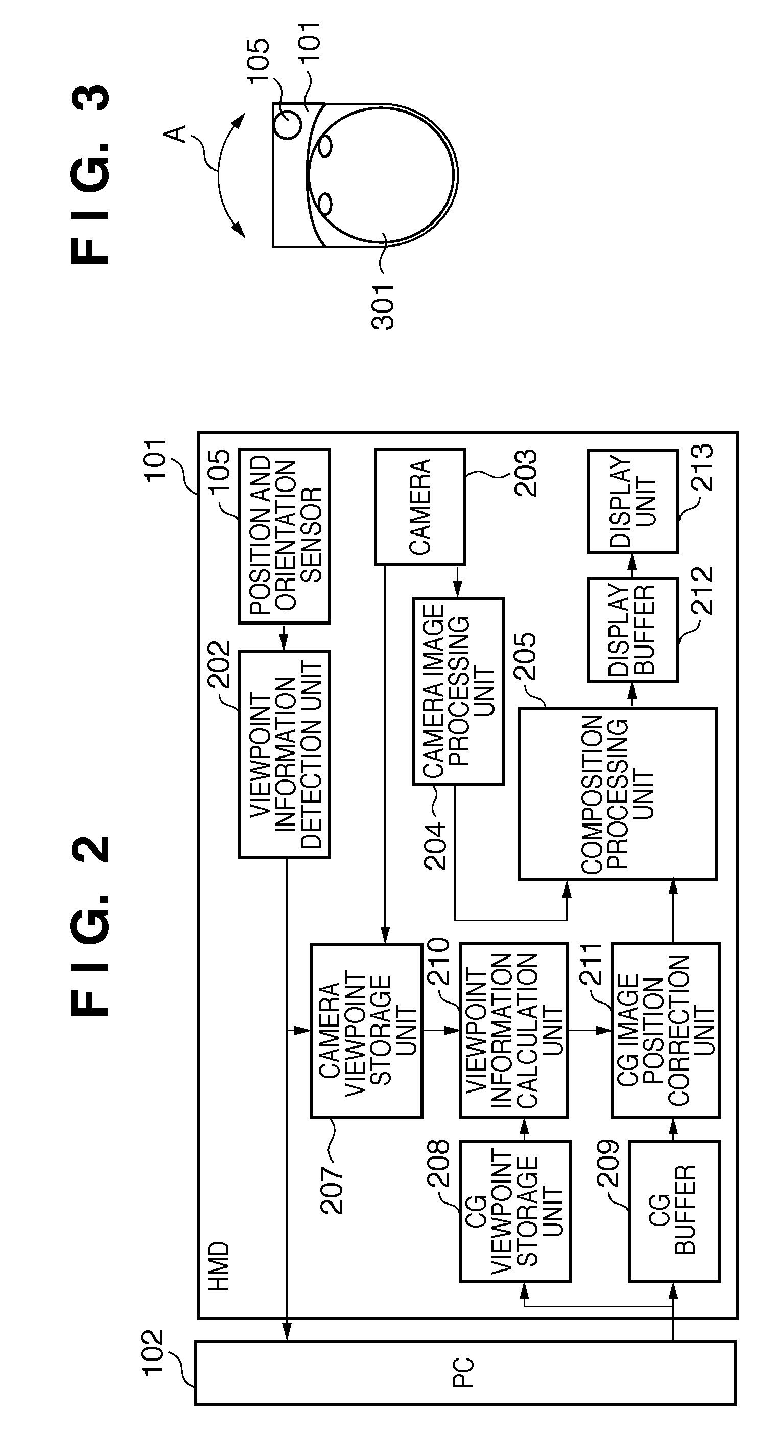
[0107]The arrangement of an HMD 101 will be described in more detail. FIG. 2 is a block diagram showing the functional arrangement of the HMD 101. In FIG. 2, the same reference numerals as those in FIG. 1 denote the same components, and a description thereof will be omitted.

[0108]Of components of the HMD 101 in FIG. 2, all the components except for a position and orientation sensor 105 are provided for each of the right and left eyes of an observer wearing the HMD 101 on the head. Although the components of the HMD 101 for one eye are shown in FIG. 2, similar components also execute operations to be described below for the other eye.

[0109]A viewpoint information detection unit 202 receives position...


PUM


Abstract

A viewpoint information calculation unit (710) calculates a difference value (α) between reference position and orientation information and position and orientation information held by a camera viewpoint storage unit (207), and a difference value (β) between the reference position and orientation information and position and orientation information held by a CG viewpoint storage unit (208). If |α|≧|β|, a physical space image is shifted by a shift amount calculated in accordance with the resolution of a display unit (213), a difference amount, and the angle of view of a camera (203), and is composited with a virtual space image. If |α|<|β|, the virtual space image is shifted by the shift amount, and is composited with the physical space image.

Description

BACKGROUND OF THE INVENTION[0001]1. Field of the Invention[0002]The present invention relates to a technique of compositing a physical space image and a virtual space image.[0003]2. Description of the Related Art[0004]In recent years, studies about an MR (Mixed Reality) technique have been extensively made (see patent reference 1). In the MR technique, a physical space image is sensed by a camera worn by an observer on the head. A virtual space image (CG (Computer Graphics) image) is generated based on viewpoint information representing the position and orientation of the viewpoint of the observer at the time of sensing. The virtual space image is composited on the physical space image to generate a composite image. The composite image is then displayed on a display device worn by the observer on the head.[0005]Processing executed in the composition process has been proposed. That is, a period of time required for creating a CG image is predicted. The amount of movement of the obser...

Claims


Application Information

Patent Timeline
IPC IPC(8): G09G5/00
CPCG02B27/017G02B2027/0138G02B2027/014G02B2027/0147G02B2027/0187G09G5/006G09G5/393G09G2340/125G09G2360/18G09G2380/02
Inventor TAKAHASHI, HIROSHI
Owner CANON KK
Why Eureka
Try Eureka