
Light guiding plate unit, surface light source apparatus and liquid crystal display apparatus

Inactive Publication Date: 2008-12-04
SUMITOMO CHEM CO LTD
View PDF9 Cites 41 Cited by
  • Summary
  • Abstract
  • Description
  • Claims
  • Application Information

AI Technical Summary

Benefits of technology

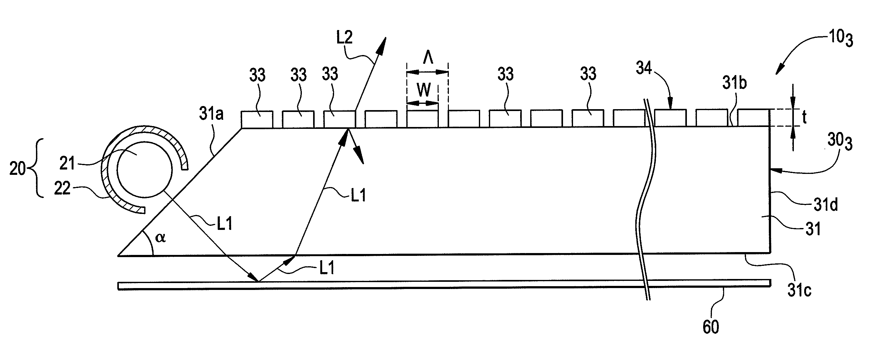
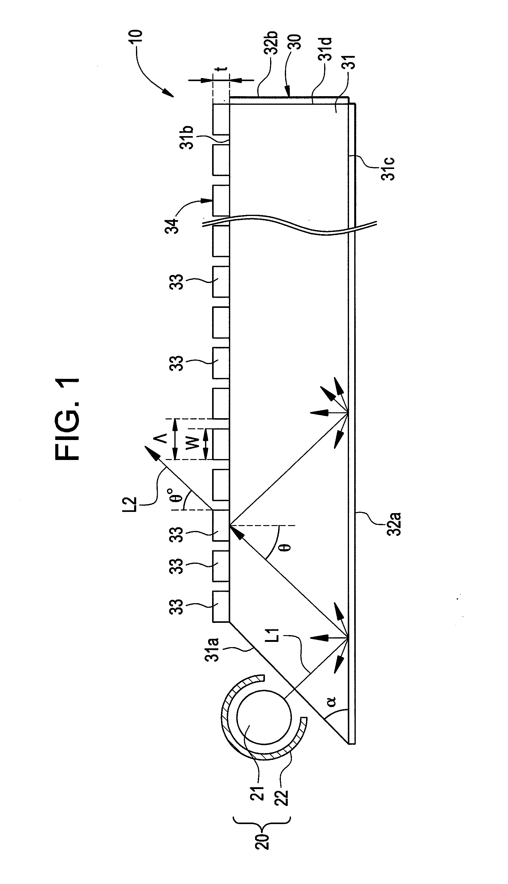
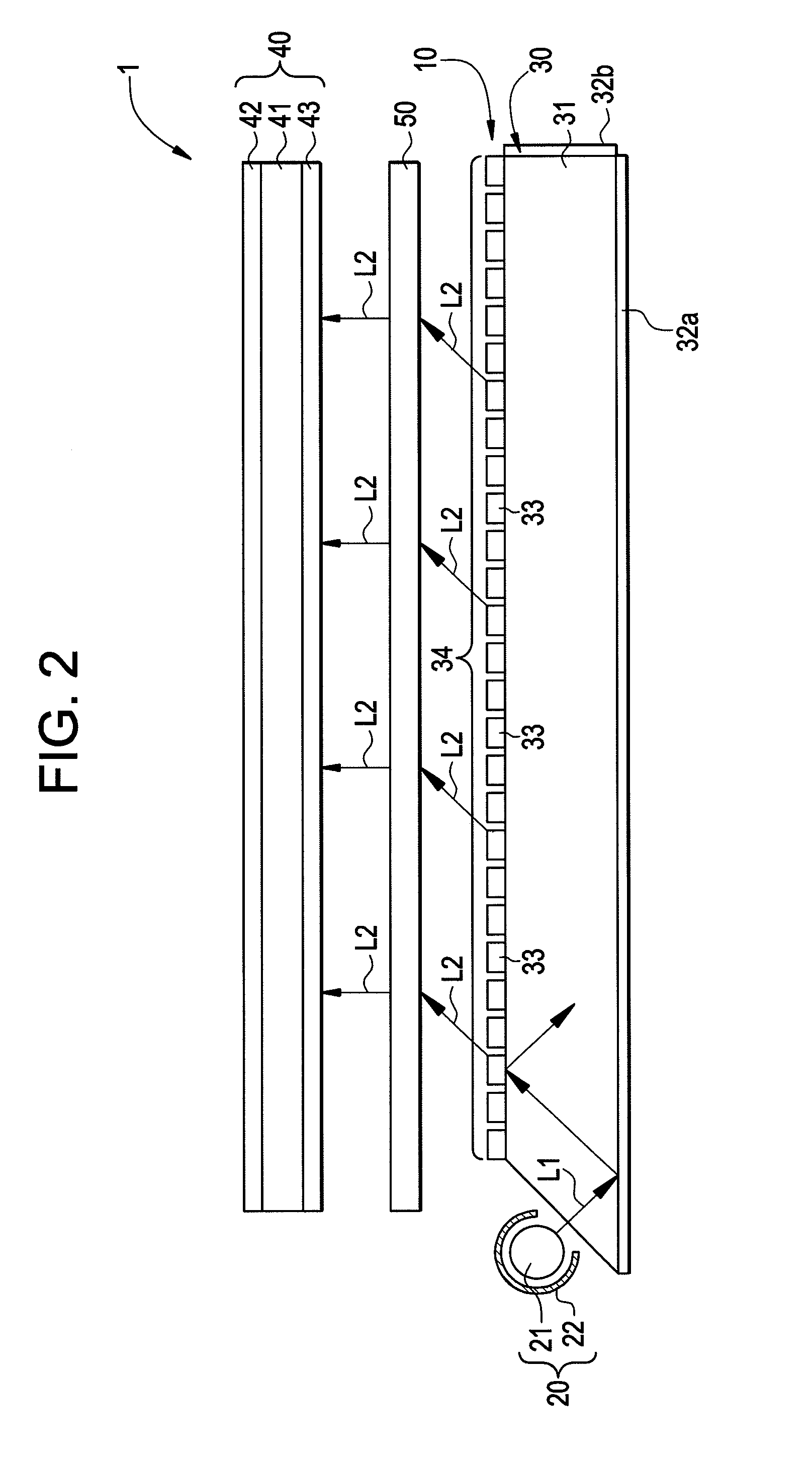
[0018]In contrast, in the light guiding plate unit, the surface light source apparatus and the liquid crystal display apparatus according to the present invention, the fill factor of the diffraction grating provided on the first surface is 0.55 or greater and 0.85 or smaller, and the transmissivity of the diffraction grating for a predetermined polarized light component (for example P-polarized light) is kept low. As a result, a larger portion of the input light returns back to the light guiding plate in comparison with the conventional case described above where the design objective is to maximize the light flux associated with the transmitted component in a predetermined state of polarization. Accordingly, the proportion of input light that can be recycled becomes larger in the proposed invention. Therefore, flux of emitted light polarized in a predetermined state is spread homogeneously over the entire output surface of the light guiding plate unit. It is not necessary to provide a new light polarizing element for reusing the non-transmitted polarized component in the liquid crystal display apparatus which includes the above described light guiding plate unit or surface light source apparatus, and therefore, reduction in the thickness of the liquid crystal display apparatus can be achieved. In addition, since the liquid crystal display unit in the liquid crystal display apparatus can be uniformly illuminated, image unevenness can be prevented.
[0023]In addition, it is preferable for the surface light source apparatus according to the present invention to further be provided with a reflecting member which is placed on the outside of the light source and reflects light emitted from the light source toward the light guiding plate side. Likewise, it is preferable for the liquid crystal display apparatus according to the present invention to further be provided with a reflecting member which is placed on the outside of the light source and reflects light emitted from the light source toward the light guiding plate side. Thus, when a reflecting member is further provided, light emitted from the light source enters into the light guiding plate in an appropriate manner. As a result, the utilization efficiency of light emitted from the light source can be increased.
[0028]Furthermore, it is preferable for the length of the metal wires in a direction normal to the plane containing the above-described diffraction grating to be approximately 400 nm or less. When the length of the metal wires in the direction of the normal of the diffraction grating plane is in the above-described range, it becomes possible to use light effectively.
[0029]In addition, it is preferable for a cross-sectional shape of the metal wires that are approximately perpendicular to the longitudinal direction of the metal wires to be square or rectangular. In the case where the metal wires have such a cross-sectional shape, it becomes easy to control the above described fill factor, and at the same time, loss of light through absorption can be reduced.
[0033]The light guiding plate unit and the surface light source apparatus that incorporates such a light guiding plate unit as described in the present invention can emit light in a predetermined state of polarization uniformly over the output surface. Furthermore, the liquid crystal display apparatus according to the present invention makes it possible for light in a predetermined state of polarization to be emitted from the surface light source apparatus of the liquid crystal display apparatus uniformly, and thus, makes it possible to prevent image unevenness.

Problems solved by technology

Light associated with the unused, orthogonal polarization component is absorbed inside the polarizing plate, reducing the light utilization efficiency.
Hence light guiding plates equipped with conventional wire grid polarizers on output surface can not guarantee uniformity of emitted flux over the entire output surface.

Method used


Image

  • Light guiding plate unit, surface light source apparatus and liquid crystal display apparatus
  • Light guiding plate unit, surface light source apparatus and liquid crystal display apparatus
  • Light guiding plate unit, surface light source apparatus and liquid crystal display apparatus

Examples


Embodiment Construction

[0044]In the following, the light guiding plate unit, the surface light source apparatus and the liquid crystal display apparatus according to embodiments of the present invention are described in reference to the drawings. Herein, the same symbols are attached to the components that are same as in the description of the drawings, and the same descriptions are not repeated. In addition, the proportions in the drawings do not necessarily correspond to those mentioned in the description.

[0045]FIG. 1 is a schematic side view showing the configuration of the surface light source apparatus according to one embodiment of the present invention. The surface light source apparatus 10 is an edge-lit type apparatus consisting of a light source unit 20 and a light guiding plate unit 30, and the light source unit 20 is located on one side of the light guiding plate unit 30. The surface light source apparatus 10 is appropriate for use as a backlight for liquid crystal display apparatuses, particu...


PUM


Abstract

A light guiding plate unit which can emit uniform light of a predetermined polarization, a surface light source apparatus and a liquid crystal display apparatus are provided. A light guiding plate unit is provided with a light guiding plate which can guide light and has a first surface from which light is emitted and a diffraction grating which is provided on the first surface of the light guiding plate, and the diffraction grating is formed of a number of metal wires in straight lines which are aligned in a direction approximately perpendicular to the long axis of the metal wires, and the length w of the metal wires in the direction in which the number of metal wires are aligned is approximately 55% or more and approximately 85% or less of the spatial period of the diffraction grating. Thus, the ratio of the length w of the metal wires to the spatial period is set to 0.65 or higher and 0.85 or lower, and thus, it is possible to control the amount of transmission of light in a predetermined state of polarization through the diffraction grating formed on the first surface.

Description

BACKGROUND OF THE INVENTION[0001]1. Field of the Invention[0002]The present invention relates to a light guiding plate unit, a surface light source apparatus and a liquid crystal display apparatus.[0003]2. Description of the Related Art[0004]A liquid crystal display (LCD) device typically includes a liquid crystal display apparatus. The liquid crystal display apparatus has a liquid crystal display unit and a surface source apparatus placed on the rear surface side (bottom side) of the liquid crystal display unit. The liquid crystal display unit comprises of a liquid crystal display panel and a pair of polarizing plates placed on the top and bottom surfaces of the liquid crystal display panel respectively.[0005]The above mentioned surface source apparatus typically has a ‘backlight’ unit. The backlight unit can either be edge-lit type or back-lit type. Edge-lit type surface source apparatuses are commonly used in liquid crystal display apparatuses used in mobile phones, and laptop pe...

Claims


Application Information

Patent Timeline
IPC IPC(8): F21V7/04G02F1/1335
CPCG02B5/3058G02B6/0015G02B6/0033G02B6/0043G02B6/0056G02F1/133615G02F1/1335G02B6/00
Inventor BANERJEE, SASWATEE
Owner SUMITOMO CHEM CO LTD
Learn More