
Apparatus for searching for and detecting defects in parts by endoscopy

a technology of endoscopy and endoscope, which is applied in the direction of instruments, spectrometry/spectrophotometry/monochromators, optical radiation measurement, etc., can solve the problems of limiting the use of instruments, not enabling observation to be performed reliably, and inability to detect defects. , to achieve the effect of good performan

Active Publication Date: 2008-12-04
SN DETUDE & DE CONSTR DE MOTEURS DAVIATION S N E C M A
View PDF21 Cites 7 Cited by
  • Summary
  • Abstract
  • Description
  • Claims
  • Application Information

AI Technical Summary

Benefits of technology

The invention provides a solution for detecting defects on parts that are difficult to access. The apparatus combines the techniques of endoscopy and penetration testing, while avoiding the drawbacks of known means. It includes a cylindrical rod with small diameter for passing through an endoscope orifice in the wall, pipes for depositing penetration test substances on a portion of the part, and a first endoscope for observing the portion in visible light. The apparatus also includes a second endoscope for observing the part in ultraviolet light, independent of the first endoscope. The light guide and image transmission means of the first endoscope are a small diameter optical fiber cable and a set of optical components including an image-forming objective lens and image-transferring lenses. The apparatus can be easily and inexpensively produced.

Problems solved by technology

Nevertheless, the ability to detect defects is limited by the resolution of the optical system of the endoscope, by the illumination, by the orientation of the endoscope relative to the surface under observation, and by the nature of the defects, amongst other things.
The outlets of the spray pipes are necessarily axial, as are the outlets for illumination and for the observation means, thereby greatly restricting the use of the instrument.
In addition, the section of the observation light pipe is very small, since said pipe must leave sufficient space inside the sheath to enable the quartz tube and the pipes for feeding and spraying penetration test substances to be installed, such that when the instrument is used with ultraviolet illumination, it can pick up only a small fraction of the light emitted by the penetration test substances, and therefore does not enable observation to be performed reliably.

Method used


Image

  • Apparatus for searching for and detecting defects in parts by endoscopy
  • Apparatus for searching for and detecting defects in parts by endoscopy
  • Apparatus for searching for and detecting defects in parts by endoscopy

Examples


Embodiment Construction

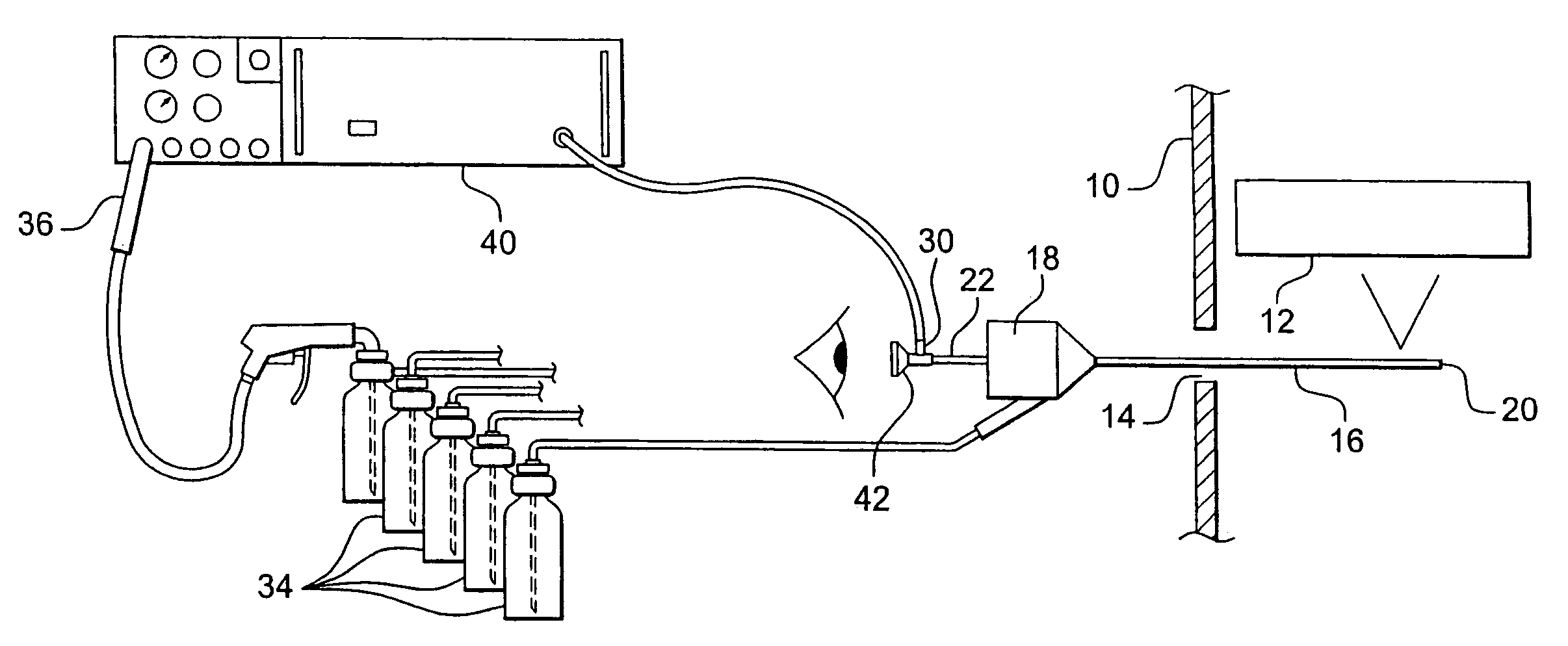
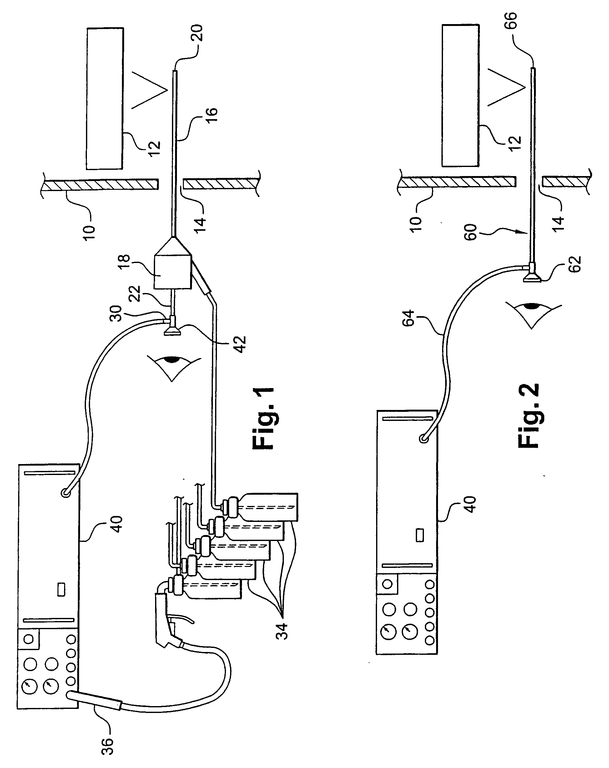
[0030]In FIG. 1, reference 10 designates a wall such as 15 a turbomachine casing behind which there are parts 12 for examination such as the rotor blades of the turbomachine.

[0031]The wall 10 includes an endoscope orifice 14 of small size (typically having a diameter of 9 mm), through which it is possible to insert a rod 16 for illuminating with visible light and for spraying penetration test substances, one end of the rod being provided with a block 18 for connection to means for supplying penetration test substances and compressed air, and its other end 20 being designed to be brought up to face a surface of the part 12 for examination.

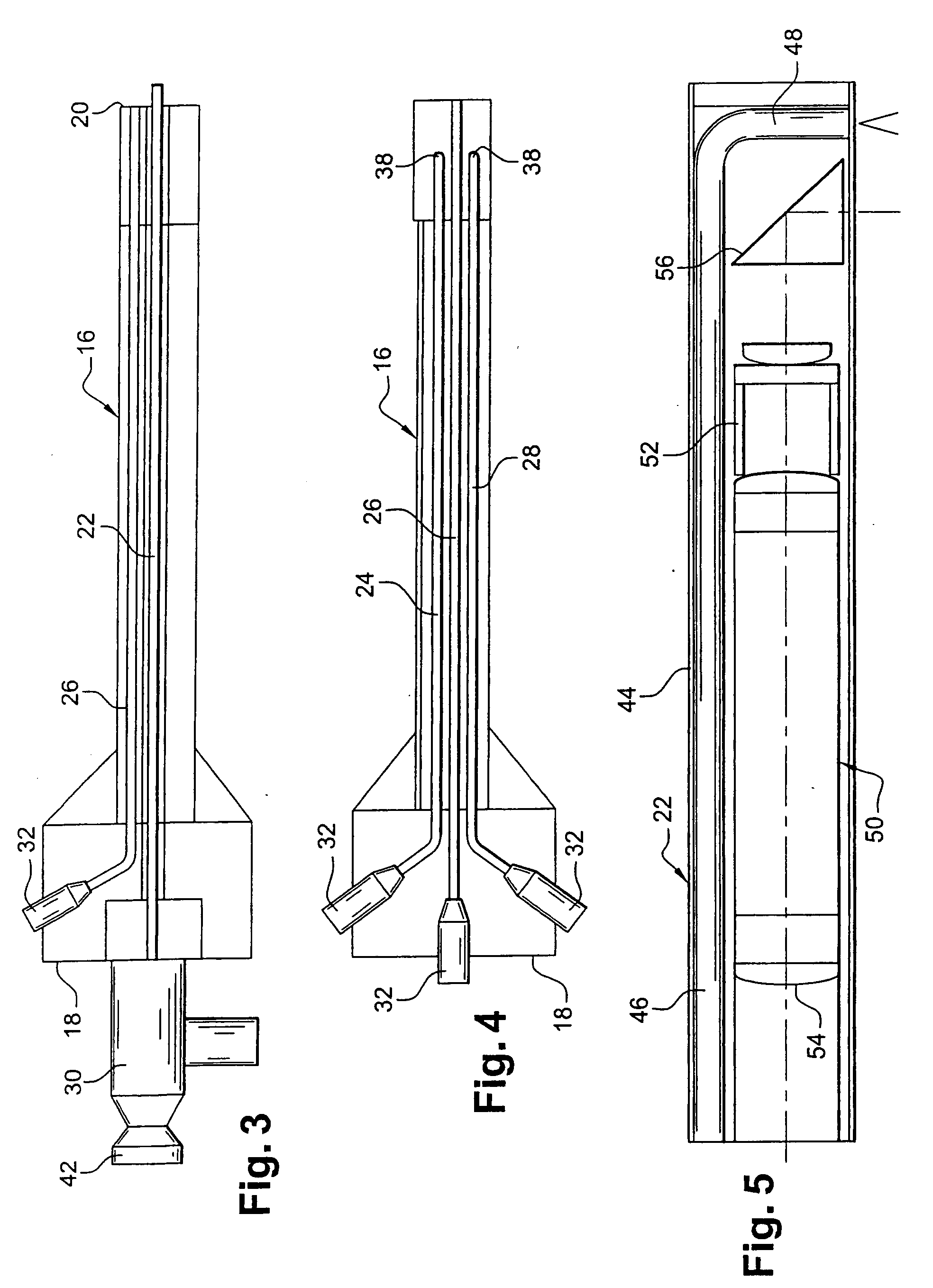
[0032]The rod 16 is shown in greater detail in FIGS. 3 and 4. The rod is a rigid tubular cylinder, e.g. made of metal, and contains a first endoscope 22 for illuminating and observing in visible light, a pipe 24 for feeding and spraying a powder on the surface of the part 12 to be examined, a pipe 26 for feeding compressed air, and a pipe 28 for fee...


PUM

PropertyMeasurementUnit
diameteraaaaaaaaaa
diameteraaaaaaaaaa
diameteraaaaaaaaaa

Abstract

Apparatus for searching for and detecting defects on parts that are substantially inaccessible, being located behind a wall, the apparatus comprising a first endoscope for illumination in visible light and for observation, the first endoscope and pipes for feeding and spraying penetration test substances being housed together in a rod which can be passed through an orifice in the wall in order to examine a part, the apparatus further comprising a second endoscope independent of the first endoscope and the rod for illuminating in ultraviolet light and for observing the portion of the part that has been treated by the penetration test substances.

Description

CROSS REFERENCE TO RELATED APPLICATIONS[0001]The present application is a Divisional Application of U.S. Ser. No. 10 / 880,502, filed Jul. 1, 2004, which is hereby incorporated herein by reference in its entirety, and claims the benefit of priority from the French patent application No. 03 08156 filed Jul. 4, 2003.BACKGROUND OF THE INVENTION[0002]1. Field of the Invention[0003]The invention relates to endoscopic apparatus for searching for and detecting defects in parts that are substantially inaccessible, being located behind a wall.[0004]2. Description of the Background[0005]It is already known to inspect internal components of equipment or a machine by means of an endoscope, i.e. an elongate optical instrument of small diameter that is passed through a small orifice in a wall in order to examine the appearance of components that are located on the other side of the wall. This makes it possible in particular to inspect the blades of a turbomachine such as an airplane turbojet or tur...

Claims


Application Information

Patent Timeline
Patent Type & Authority Applications(United States)
IPC IPC(8): G01N21/00G02B23/26A61B1/00G01N21/91G02B23/00G02B23/24
CPCG01N21/91G02B23/2469
Inventor BONNINGUE, ISABELLELE QUELLEC, JOHNLEMOAL, JEAN-CLAUDEBACCELLA, MICHEL
Owner SN DETUDE & DE CONSTR DE MOTEURS DAVIATION S N E C M A
Learn More