Image display apparatus

a technology of image display and display screen, which is applied in the field of image display screen, can solve the problems of increasing the cost, inhibiting the miniaturization of optical scanners, and large size of the drive mechanism, and achieves the effect of facilitating the determination of a proper first frequency and facilitating the provision of a stable image display

Inactive Publication Date: 2008-12-04
KONICA MINOLTA OPTO
View PDF1 Cites 44 Cited by
  • Summary
  • Abstract
  • Description
  • Claims
  • Application Information

AI Technical Summary

Benefits of technology

[0019]This facilitates the determination of a proper first frequency.
[0020]It is thus an object of the invention to provide an image display apparatus that facilitates the provision of a stable image display by beam raster scanning accompanied with resonant oscillations in the main scanning direction.

Problems solved by technology

Such optical scanners require mechanical drive mechanisms for driving a mirror with a motor or with an electromagnetic actuator; however, such drive mechanisms are relatively large in size and expensive, inhibiting miniaturization of the optical scanners and increasing the cost thereof.
However in horizontal scanning where in general a mirror makes resonant oscillations for a horizontal scan output of greater amplitude, it is not easy to match the resonant frequency (horizontal scanning frequency) of the resonant oscillations and the horizontal synchronizing frequency of the image signal for synchronization.
The technique described in the above paragraph (i), however, may cause substantial changes in the output of horizontal scanning (horizontal scan width) with fluctuations in the resonant frequency due to environmental changes such as temperature or changes with time, thereby having difficulty in providing a stable image display by beam raster scanning accompanied with resonant oscillations in the horizontal scanning direction (the main scanning direction).
The technique described in the above paragraph (iii), although capable of controlling the resonant frequency, necessitates a complicated structure for that control.

Method used


Image

  • Image display apparatus
  • Image display apparatus
  • Image display apparatus

Examples


first preferred embodiment

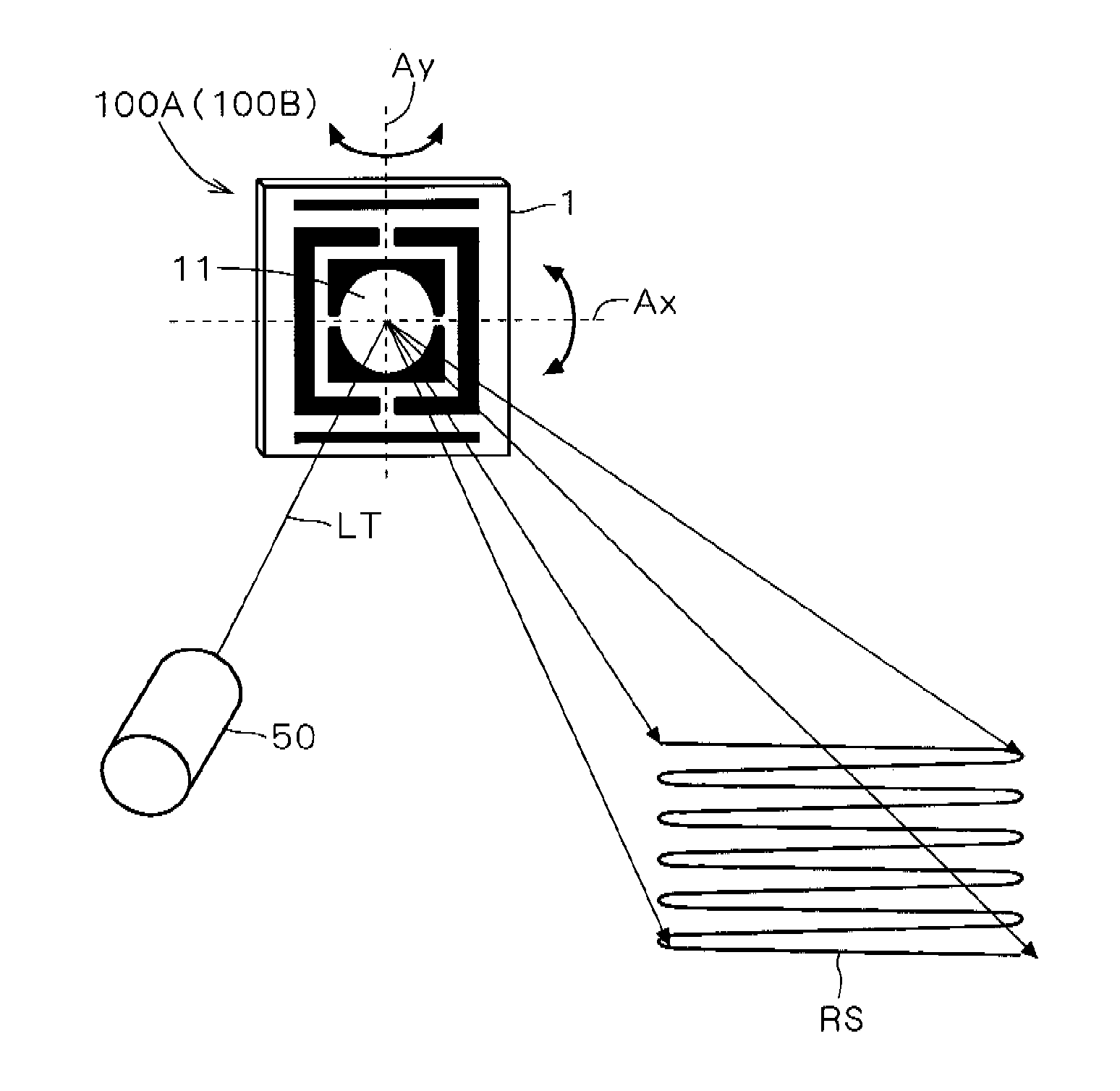
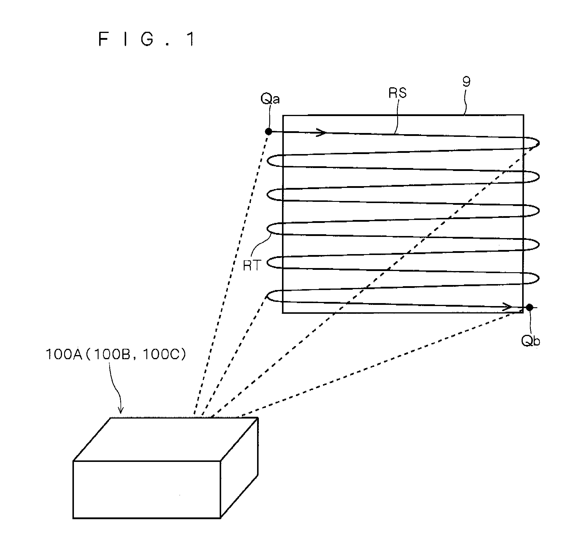
[0043]FIG. 1 is an external view of an image display apparatus 100A according to a first preferred embodiment of the invention.

[0044]The image display apparatus 100A has a box-like shape and is configured as a projector that projects video (images) onto a screen 9. This image display apparatus 100A performs raster scanning RS of light beams emitted onto the screen 9 which is a plane of projection, thereby allowing a display of two-dimensional images on the screen 9. The raster scanning RS completes one image display by continuous scanning of light beams, for example from a start position Qa at the top of a displayed image to an end position Qb at the bottom of the displayed image. When the light beam scanning arrives at the position Qb, then vertical (and horizontal) scanning is performed for return to the position Qa in order for the next image display, during a vertical blanking interval where no image is displayed.

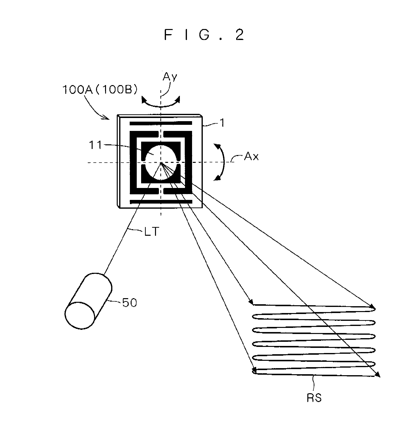
[0045]The image display apparatus 100A is provided therein with an...

second preferred embodiment

[0148]An image display apparatus 100B according to a second preferred embodiment of the invention has a similar configuration to the image display apparatus 100A of the first preferred embodiment shown in FIGS. 1 to 3, but differs in the structure of its horizontal drive controller.

[0149]Specifically, an image-signal controller 520 and a horizontal drive controller 60a in the image display apparatus 100B are configured to store a program or the like for executing operations described below.

520>

[0150]The image-signal controller 520 has a similar configuration to the image-signal controller 52 of the first preferred embodiment shown in FIG. 11, but it utilizes this configuration for a different operation from the one described in the first preferred embodiment. To be concrete, in the raster scanning RS (FIG. 1), the image-signal controller 520 can perform, in addition to the same reciprocating-display scanning as described in the first preferred embodiment, reciprocating-display scann...

third preferred embodiment

[0166]An image display apparatus 100C according to a third preferred embodiment of the invention is analogous in configuration to the image display apparatuses 100A and 100B of the first and second preferred embodiments shown in FIG. 1, but it differs in the configuration of its optical scanner.

[0167]FIG. 20 is a plan view showing a configuration of the essential parts of an optical scanner 101 according to the third preferred embodiment of the invention.

[0168]The optical scanner 101 is a so-called MEMS (Micro Electro Mechanical Systems) mirror made by micromachining of a silicon chip. In the following, the optical scanner 101 is also referred to as an MEMS mirror 101 where appropriate.

[0169]The optical scanner 101 mainly includes a mirror 110, two torsion bars 121 and 122, a movable frame 130, an actuator part 150 consisting of four piezoelectric elements (piezoelectric actuators) 151 to 154, four erection parts 141 to 144, four narrow coupling parts 130a to 130d, and a fixed frame...


PUM


Abstract

An image display apparatus capable of displaying an image on a plane of projection by beam raster scanning associated with resonant oscillation in a horizontal scanning direction (the main scanning direction), includes a resonance-point detector for detecting a mechanical resonant frequency in the horizontal scanning direction. Out of frequencies that are multiples of a vertical synchronizing frequency in image display, for example a frequency nearest to the mechanical resonant frequency detected in the resonance-point detector is determined as a horizontal scanning frequency of the raster scanning. The image display apparatus can thus provide a stable image display with ease.

Description

[0001]This application is based on Application Nos. 2007-140193 and 2008-080722 filed in Japan, the contents of which are hereby incorporated by reference.BACKGROUND OF THE INVENTION[0002]1. Field of the Invention[0003]The present invention relates to an image display apparatus capable of displaying an image on a given plane of projection by beam raster scanning.[0004]2. Description of the Background Art[0005]Optical scanners deflecting and scanning light beams such as laser beams are utilized for optical equipment such as a barcode reader, a laser printer, and a display. Some such optical scanners include a polygon mirror scanning reflected light by rotation of a polygonal shaped mirror with a motor, a galvano-mirror causing a plane mirror to rotate and oscillate with an electromagnetic actuator, or the like. Such optical scanners require mechanical drive mechanisms for driving a mirror with a motor or with an electromagnetic actuator; however, such drive mechanisms are relatively ...

Claims


Application Information

Patent Timeline
Patent Type & Authority Applications(United States)
IPC IPC(8): G02B26/10
CPCG02B26/0858G02B26/101
Inventor MIZUMOTO, KENJI
Owner KONICA MINOLTA OPTO
Why Eureka
Try Eureka