Eureka AIR delivers breakthrough ideas for toughest innovation challenges, trusted by R&D personnel around the world.

Apparatus and method for providing an insulated support rack

a technology for supporting racks and cables, applied in electrical apparatus, substation/switching arrangement details, standard structures, etc., can solve problems such as affecting the insulation of existing support racks, affecting the quality or durability of the support rack, and affecting the safety of users

Inactive Publication Date: 2008-12-04
FOX IV RICHARD J
View PDF4 Cites 5 Cited by
  • Summary
  • Abstract
  • Description
  • Claims
  • Application Information

AI Technical Summary

Benefits of technology

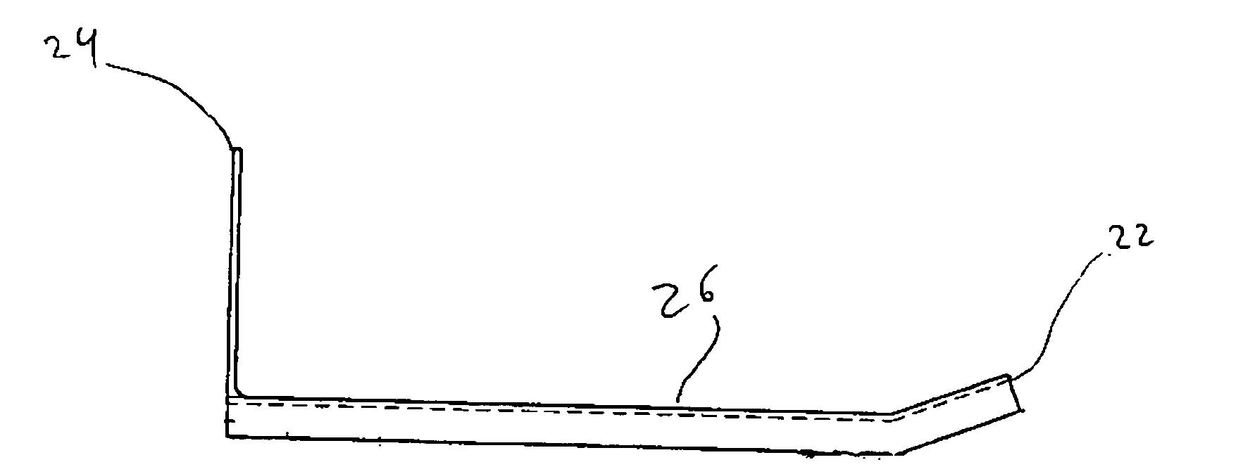
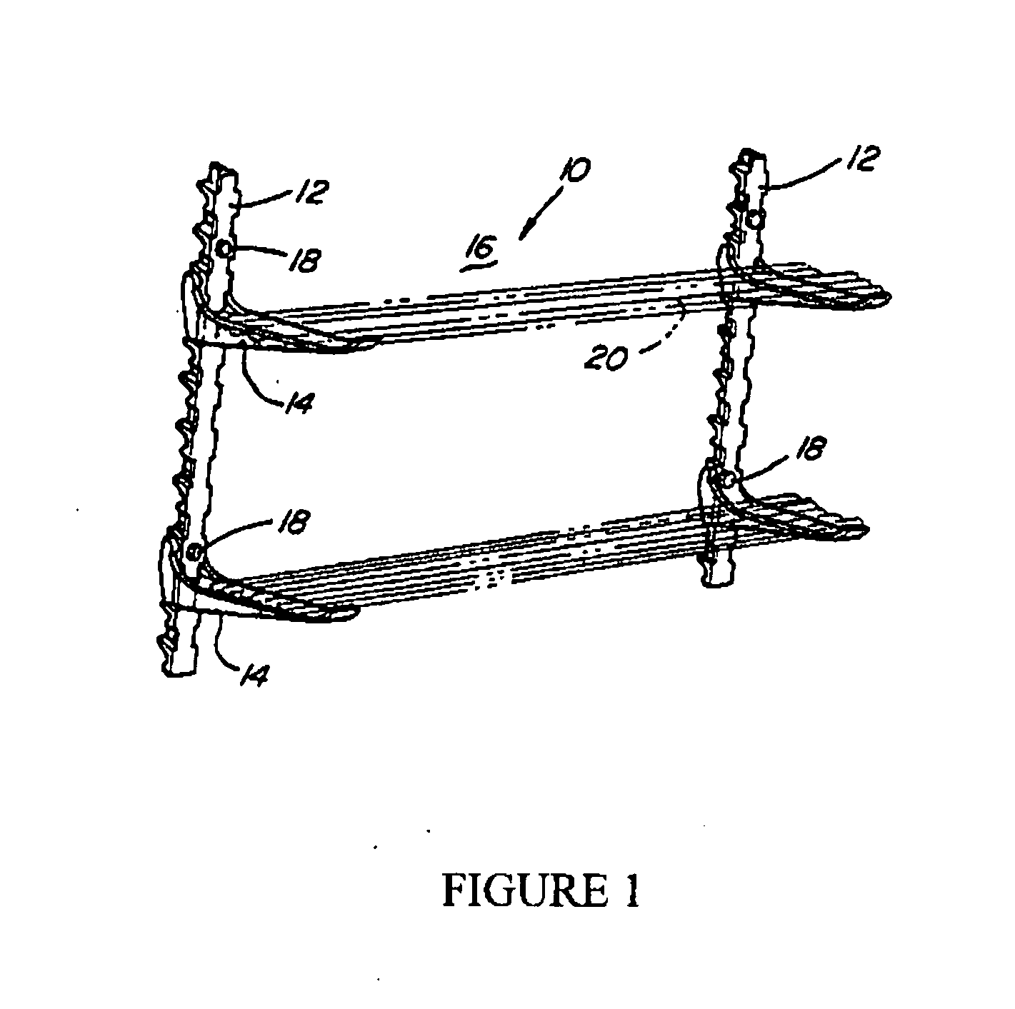
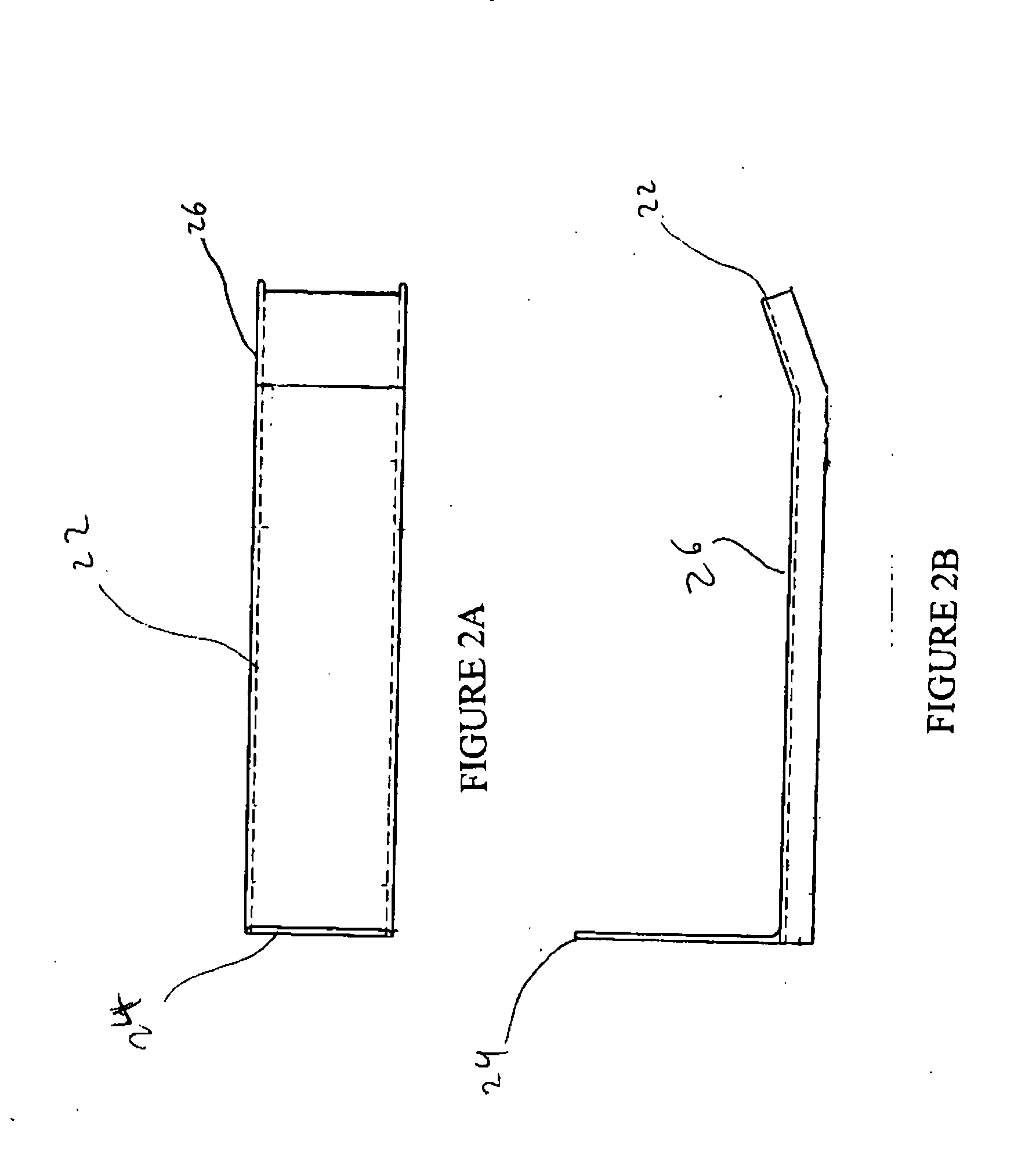
[0014]The present invention provides an apparatus to facilitate the insulation of existing support racks by providing an insulated cover to shield existing steel support racks from stray or surging voltage. In this way, the present invention enables users to continue to utilize existing support rack systems without sacrificing the level of quality or durability that is customary in current field applications. The rack arm cover is a safeguard to preventing faults at points of cable insulation wear or failure resulting in failure as the rack arm and stanchion may be energized. In addition, the rack arm cover of the present invention safeguards against stray voltage occurrences that could be the result of electrical wires interacting with exposed conductive parts such as vault gratings.
[0015]The present invention also provides a method for installing such insulated covers in order to utilize and protect existing steel support racks from stray or surging voltage thereby providing a cost-effective and safe field application.

Problems solved by technology

It is preferred in the art that the cables are installed in underground locations as the cables are often considered unsightly and can be dangerous if humans interfere with the cables.
Further, one of ordinary skill in the art can easily recognize that such cables incur damage when installed in above-ground locations such as attached to common telephone / electrical poles or other like through structures due to the influences of environmental changes, primarily climatic fluctuation.
While it is desirable to install cables underground to protect the cables from human interference and to protect humans from interaction with the cables as well as other common above-ground hazards, the underground location does not prevent all problems.
For example, environmental factors such as temperature, moisture, humidity, precipitation, and flooding are always potential dangers.
In addition, underground vermin typically destroy cable components, including insulation required to protect the cables and the electrical conduits.
Vermin are especially destructive to cable runs and assemblies if the runs and assemblies are positioned at points in close proximity to the ground or easily accessible from the ground.
As a result, underground utility lines in typical installations generally require extra insulation due to the harsh underground environment.
In addition, the racks must be constructed of sufficiently strong material to withstand considerable vibration as the cable runs are frequently strung through passages beneath vehicular roadways, train thruways, or other points subject to heavy vibration.
These voltage levels of varying voltages are extremely dangerous to workers.
However, existing systems provide insulation by using expensive, impractical systems and methods.
First, the systems are expensive to manufacture, install, and replace.
Second, the systems are ineffective in providing adequate strength to support heavy cables and are ineffective in providing adequate protection to workers as they often fail to properly adhere to existing cable rack systems, become unraveled, or deteriorate over time.
Finally, these systems fail to provide an adequate apparatus and method for retrofitting existing systems and are only useful in new cable run assemblies.
In addition, wrapping tape around a support rack interferes with the support and load-balancing properties with which support racks are designed.
The tape is also subject to the wear and tear associated with the underground conditions and often tears, unravels, or is otherwise rendered ineffective.
Further, installing wrapping tape in the field requires extensive manual labor which is often expensive and subject to irregular application in the confined space of an underground cable installation such as a cable vault.
Finally, the elimination or reduction of stray voltage concerns are not addressed.
Stray voltage occurs when electrical wires accidentally come in contact with exposed conductive parts like vault gratings which may cause injuries and fatalities to members of the public.
There are, however, disadvantages associated with this solution.
First, the potential for failure of such a system to operate due to malfunction or corrosion-related damage is a prominent problem in the field.
In addition, the material and labor costs associated with procuring and implementing the installation of such a grounding mechanism for each existing support rack is generally prohibitive.
Further, the application of this type of grounding mechanism yields an added step during the installation in the field which may be difficult and impractical for certain installations depending on particular environmental or structural characteristics.
In addition, it is likely that overtime, stray currents may follow alternate paths with less resistance should such paths become available.
Finally, one of ordinary skill in the art will readily recognize that since the rack / stanchion are already grounded (i.e., the rack and stanchion combination are bolted into the wall of the vault), this application fails to prevent a fault between the cable and the ground.
One disadvantage of the system disclosed by Wolfbauer is the replacement of a steel product with a plastic product, thereby sacrificing quality and durability.
Due to the extended lengths of cable runs and the heavy installation and material components of cables or cable conduits, plastic-based rack systems are subject to strength deficiencies and may also be subject to sudden calamitous failure.
Further, due to the intense vibration associated with underground installations located below vehicular roadways, plastics and related materials are not of sufficient strange to provide long-term support for cables and cable conduits.
Also, as with other solutions, due to the additional materials and labor costs associated with installation installing non-conductive support racks is an untenable solution.
Further, in certain instances, field conditions may require a malleable construction rather than a plastic construction which if bent may quickly shear at a particular stress point resulting in product failure and increased labor and material costs.
It is also apparent in the art that rack systems of this nature that are primarily plastic, fiberglass, or some combination thereof, are often expensive to manufacture and install and as a result are cost-prohibitive in the art.
It is evident that a porcelain cover is non-conductive but several disadvantages of this application are evident.
For example, one disadvantage of this potential solution is the fragile nature of porcelain, which can crack under the heavy loads carried by support racks.
Further, porcelain construction is often expensive.
In addition, similar to the previous solution, a porcelain covered product is susceptible to shearing in the field should field conditions require any manipulation of the device.

Method used


Image

  • Apparatus and method for providing an insulated support rack
  • Apparatus and method for providing an insulated support rack
  • Apparatus and method for providing an insulated support rack

Examples


Embodiment Construction

[0025]A detailed illustrative embodiment of the present invention is disclosed herein. However, techniques, systems and operating structures in accordance with the present invention may be embodied in a wide variety of forms and modes, some of which may be quite different from those in the disclosed preferred embodiment and alternate embodiments.

[0026]Consequently, the specific structural and functional details disclosed herein are merely representative, yet in that regard, they are deemed to afford the best embodiment for purposes of disclosure and to provide a basis for the claims herein which define the scope of the present invention. The following presents a detailed description of a preferred embodiment (as well as some alternative embodiments) of the present invention.

[0027]Moreover, well known methods, procedures, and substances for both carrying out the objectives of the present invention and illustrating the preferred and alternate embodiments are incorporated herein but ha...


PUM


Abstract

A system and method are disclosed for providing an improved rack arm system wherein insulating material is utilized to guard against stray voltage. The system and method entail providing insulated rack arm systems for installation in new locations as well as a snap-on insulating piece for utilization with existing rack arm systems.

Description

FIELD OF THE INVENTION[0001]The present invention generally relates to the field of support systems for cables, including power and communication cables. More specifically, the present invention relates to an apparatus and method for insulating existing support racks supporting such cables, primarily in underground conduits providing access to generation points and termination points in various structures such as buildings, residential developments, and the like. Also the present invention relates to the creation and installation of pre-insulated support racks for supporting cables.BACKGROUND OF THE INVENTION[0002]Cables, such as electric power and other like cable systems are typically located in underground tunnels. For purposes of disclosure of the present invention herein, cables are generally referred to as any insulated conductor or combination of insulated conductors, and / or a fiber or group of fibers. Underground tunnels provide funnels to various access and termination poin...

Claims


Application Information

Patent Timeline
Patent Type & Authority Applications(United States)
IPC IPC(8): H02B1/01
CPCH04Q1/06H05K9/0062H04Q1/09
Inventor FOX, IV, RICHARD J.
Owner FOX IV RICHARD J
Why Eureka
Eureka Blog
Learn More