Method of Sensing Speed of Electric Motors and Generators

a technology of electric motors and speed sensing, which is applied in the direction of motor/generator/converter stoppers, dynamo-electric converter control, instruments, etc., can solve the problems of significant cost increase for the motor assembly, inability to measure the speed of small dc motors, and inability to use small dc motors. to achieve the effect of cost saving and simple and inexpensive circui

Inactive Publication Date: 2008-12-04
KASTNER MARK ALLEN
View PDF9 Cites 503 Cited by
  • Summary
  • Abstract
  • Description
  • Claims
  • Application Information

AI Technical Summary

Benefits of technology

[0048]One purpose of this invention is a method of sensing the speed of DC motors and generators and / or sensing the rotor position of DC motors and generators and / or sensing the number of revolutions that DC motors and generators have turned, without the need for additional mechanical components or wiring. Timing signals inherently present in the voltage and current waveforms on the brush / rotor terminals and / or the stator terminals of DC motors and generators are instead utilized to determine the speed and / or position and / or total amount of rotation of the motors and generators. A simple and inexpensive circuit is used to detect these pre-existing speed and rotor position indicating signals. Since these signals are present on the motor's existing rotor / brush terminals and / or stator terminals, no additional mechanical hardware (in the form of a speed or rotor position sensor) and no additional wiring are required. This results in a substantial cost savings and a significant reliability enhancement over other motor speed and position sensing techniques.

Problems solved by technology

However, this is not intended to imply that these examples and circuits are applicable to only permanent magnet DC motors.
Soft start controllers without speed sensing are not as effective for these loads, because the motor and load rapidly accelerate after the static friction has been overcome.
In the past it has not been practical to measure the speed of small DC motors used in inexpensive consumer applications (such as power tools, kitchen appliances, etc.) because measuring the motor speed accurately required the addition of a relatively expensive speed sensor.
These speed sensors have numerous disadvantages:1. A significant cost increase for the motor assembly, due to both the additional components and additional assembly labor.
This added cost may not be economically practical, particularly in the case of inexpensive consumer products.2. Increase in complexity for the overall motor assembly.3. The need for precise alignment between the speed wheel, light or magnetic field detector, and light source (for optical speed sensors).4. Mechanical modifications to standard motors that are required in order to mount the speed sensor components.5. Speed sensor components of different sizes are needed for motors with different physical sizes.6. Significant decrease in overall motor reliability because of added components.7. Reliability problems due to contaminants entering the required close physical spacing between the speed wheel and detector (and light source for optical speed sensors).
Added cost, complexity, and reliability concerns because of the additional electrical connections required to interface to the speed sensor.11.
Space for the sensor components may not be available within the motor.
All of these solutions are considerably more expensive than a simple brushed-DC motor.
As the market for domestic robots grows, there will be great competitive pressure to reduce their cost.

Method used


Image

  • Method of Sensing Speed of Electric Motors and Generators
  • Method of Sensing Speed of Electric Motors and Generators
  • Method of Sensing Speed of Electric Motors and Generators

Examples


Embodiment Construction

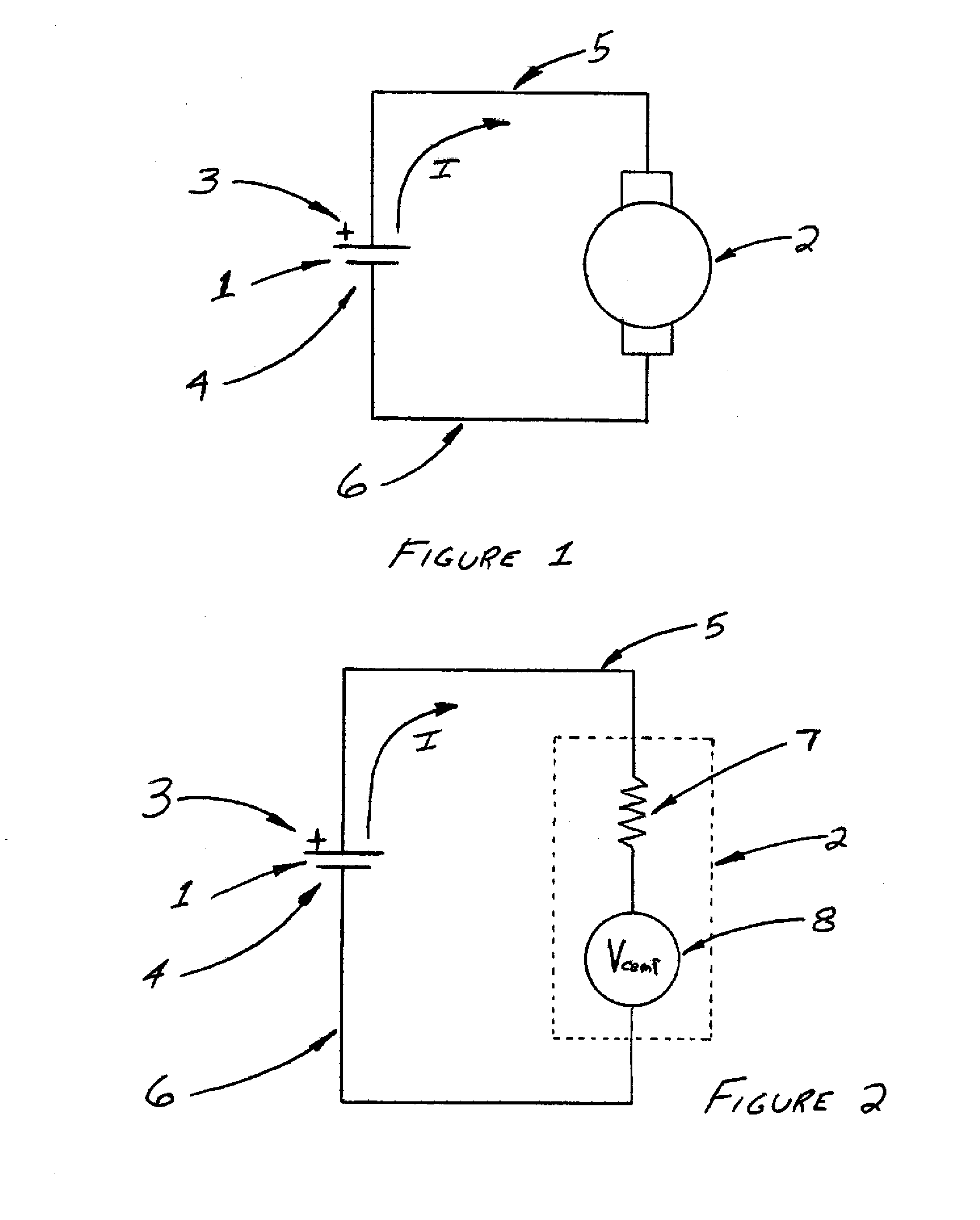
[0411]FIG. 1 shows a simplified schematic of a battery (1) powering a DC motor (2). The schematic most accurately portrays a permanent-magnet DC motor, which has rotor windings but no stator windings. However, the motor symbol shown in this schematic may also be used to generically represent any type of DC motor, including the many types that have both rotor windings and stator windings. The motor symbol in FIG. 1 is used in this generic sense in most of the figures contained within this document.

[0412]In FIG. 1 and in other figures contained herein, a single-cell battery (1) is shown as the power source for the motor (2). As per common convention, this single-cell battery symbol is used to generically represent batteries of any number of cells or voltage, and also any DC voltage source. Further, within this document, this battery symbol is used to generically represent any DC or AC power source that may be used to power a motor.

[0413]In the simplified schematic shown in FIG. 1, the...


PUM


Abstract

A method and circuit for determining the speed and/or counting the revolutions of brush and commutator motors is described. The method and circuitry detects signals present on the windings of the motor due to commutation that occurs at the brushes and commutator of the motor. This method can be used to simply monitor & indicate the motor speed and revolutions or to form the basis of a motor control.

Description

BACKGROUND OF INVENTION[0001]Electric motors and electric generators are of nearly or completely the same construction; the main difference is how they are used: a motor produces a mechanical output from an electrical input, while a generator produces an electrical output from a mechanical input. Electric motors and electric generators are collectively referred to as electrical machines. In most cases, a motor will work as a generator and a generator will work as a motor; this is particularly true for DC motors and generators. While the bulk of this document describes the invention and the supporting material with reference to use with DC motors, a person skilled in the art will recognize that both the invention and the supporting material apply equally to electric machines in general, including motors and generators used in both AC and DC applications.[0002]Commutator electric motors and generators use one or more pairs of electrically-conductive brushes sliding on a rotating commu...

Claims


Application Information

Patent Timeline
Patent Type & Authority Applications(United States)
IPC IPC(8): H02P7/29G01P3/46H02P7/06
CPCG01P3/44G01P3/48G01P3/484H02P7/2913H02P7/0094
Inventor KASTNER, MARK ALLEN
Owner KASTNER MARK ALLEN
Why Eureka
Try Eureka