
Battery module

a battery module and battery technology, applied in the field of batteries, can solve the problems of difficult to apply uniform pressure to each battery, battery capacity loss and cycle performance deterioration, and the pressure applied tends to vary between the batteries positioned at both ends and those positioned in the vicinity of the center, so as to prevent the distance between the electrodes from increasing, reduce the loss of battery capacity and cycle performance deterioration, and efficiently release the effect of high-rate discharg

Inactive Publication Date: 2008-12-04
SANYO ELECTRIC CO LTD
View PDF3 Cites 32 Cited by
  • Summary
  • Abstract
  • Description
  • Claims
  • Application Information

AI Technical Summary

Benefits of technology

[0011]It is an object of the present invention to provide a battery module of prismatic batteries in which each of the batteries can be compressed uniformly and moreover heat can be dissipated efficiently from each of the batteries.
[0013]In the present invention, two plates are disposed between each of the stacked batteries, and each of the batteries is compressed by shifting the two plates in directions away from each other. As a result, each of the batteries can be compressed substantially uniformly, and the effect of preventing the distance between the electrodes from increasing can be obtained to substantially the same degree among the batteries. Thus, battery capacity loss and cycle performance deterioration can be minimized.
[0014]Moreover, since the two plates disposed between each of the batteries are shifted in directions away from each other, a space is formed between the two plates. According to the present invention, heat generated in the battery can be released from this space. As a result, the heat generated from each of the batteries during high rate discharge can be released outside efficiently, and high rate charge-discharge becomes possible.

Problems solved by technology

When the distance between the electrode plates increases, electron conductivity lowers in the positive electrode active material layer and the negative electrode active material layer, and as a consequence, the internal resistance increases, causing battery capacity loss and cycle performance deterioration.
A problem with such methods of compressing the batteries is that it is difficult to apply a uniform pressure to each of the batteries.
In particular, when the number of the stacked batteries is large, the problem arises that the pressure applied tends to vary between the batteries positioned at both ends and those positioned in the vicinity of the center.
Thus, the internal resistance rises in some of the batteries, and consequently, battery capacity loss and cycle performance deterioration tend to occur easily.
During high rate discharge, each of the batteries generates heat, but in the conventional battery module structures, the heat cannot be dissipated sufficiently.
In some cases, the battery temperature rises to the upper limit of the operating temperature range, causing the battery to fail to discharge.
This type of battery module also has the problem that it is difficult to apply a uniformly pressure to each of the batteries because the batteries are pressed by the heat sinks disposed at both ends.
Moreover, heat dissipation from each of the batteries is not sufficient, so the problem of the battery temperature elevation also remains unresolved.

Method used


Image

  • Battery module
  • Battery module
  • Battery module

Examples


example 1

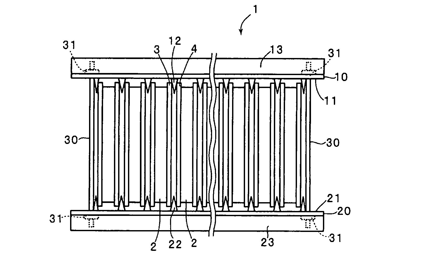
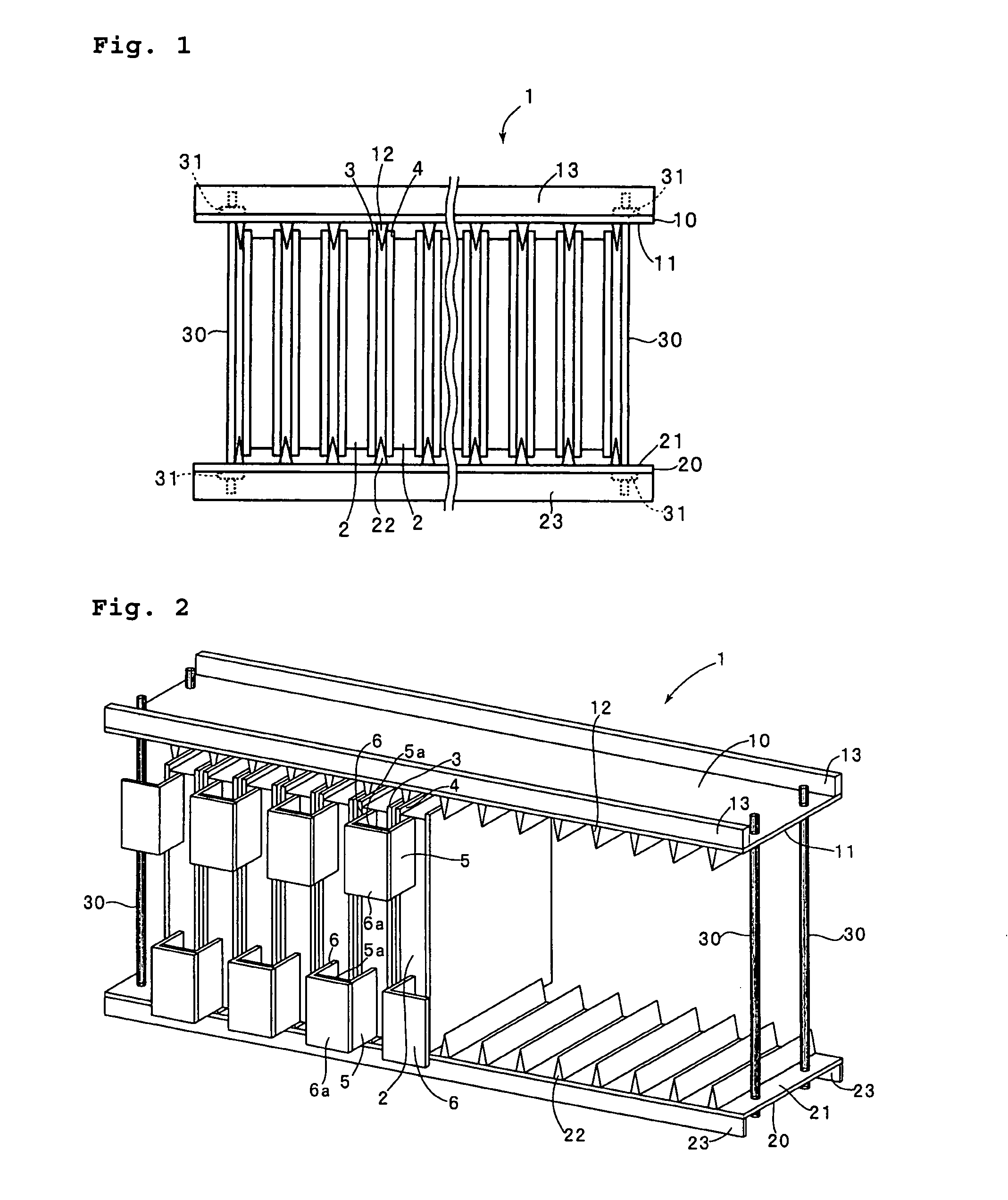
[0053]FIG. 1 is a side view of the battery module prepared in Example 1, and FIG. 2 is a perspective view thereof.

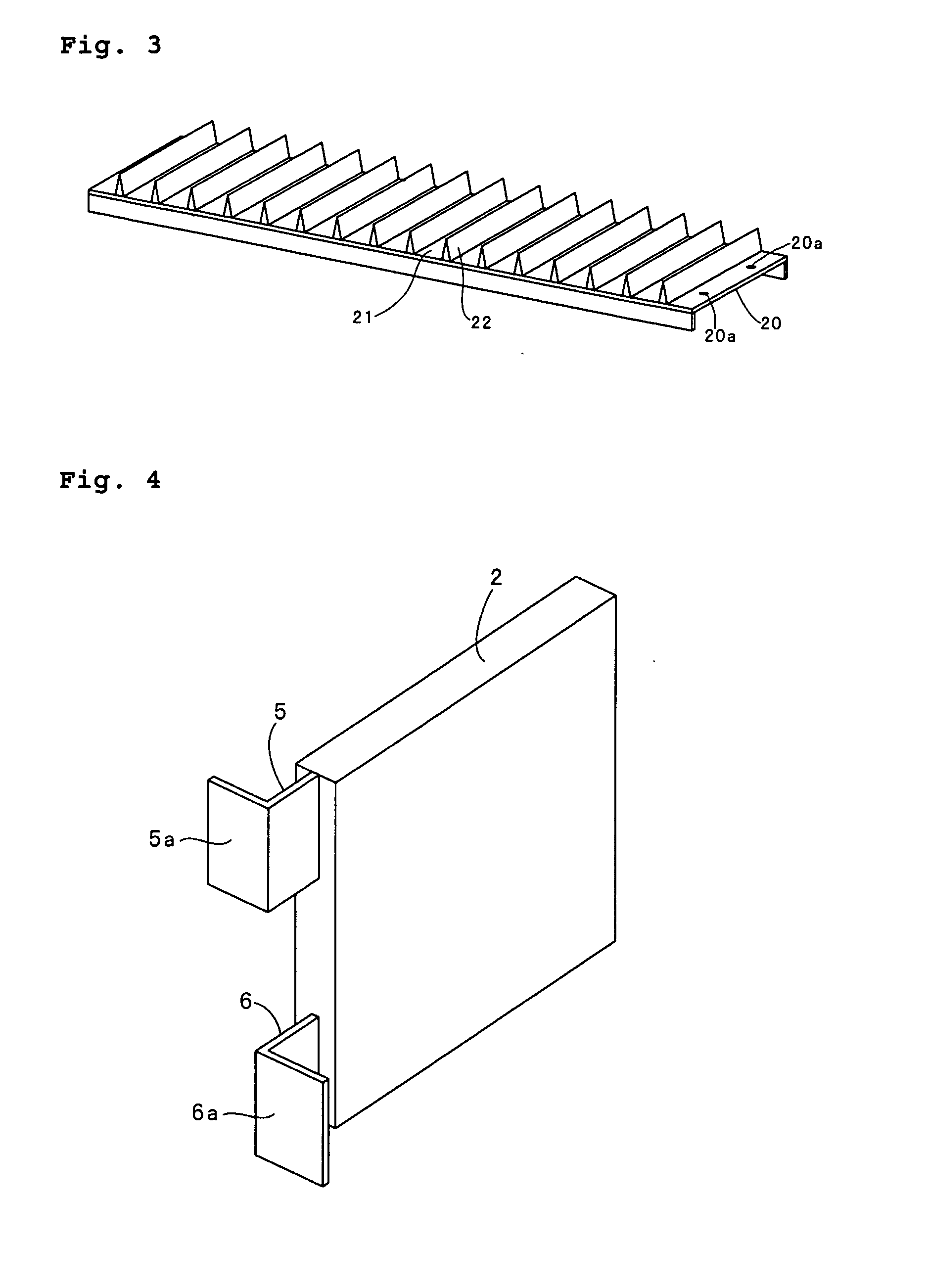
[0054]As illustrated in FIGS. 1 and 2, the battery module of the present example comprises stack electrode batteries 2 stacked in a thickness direction, and two plates 3 and 4 are inserted between each of the batteries 2. Each of the plates 3 and 4 is formed of stainless steel and has a width of 100 mm, a height of 115 mm, and a thickness of 2 mm.

[0055]A pair of frame members 10 and 20 are provided so as to sandwich the batteries 2 along a direction perpendicular to the stacking direction of the batteries 2. The frame members 10 and 20 have respective opposing surfaces 11 and 21 opposed to each other, and the frame members 10 and 20 are disposed so that the opposing surfaces 11 and 21 face each other. Wedge-shaped spacers 12 and 22 are provided on the opposing surfaces 11 and 21, respectively. The wedge-shaped spacers 12 and 22 have a triangular prismatic shape. Each of ...


PUM

PropertyMeasurementUnit
widthaaaaaaaaaa
thicknessaaaaaaaaaa
widthaaaaaaaaaa

Abstract

A battery module has a plurality of prismatic batteries (2) stacked in a thickness direction. Two plates (3, 4) are provided between each of the batteries (2), and each of the batteries (2) is compressed by shifting the two plates (3, 4) in directions away from each other. A pair of frame members (10, 20) having opposing surfaces (11, 21) extending along the stacking direction of the batteries (2) are disposed face to face so as to sandwich the batteries (2) in a direction perpendicular to the stacking direction of the batteries. Wedge-shaped spacers (12, 22) inserted between the two plates (3, 4) are provided respectively on the opposing surfaces. By narrowing the gap between the pair of frame members (10, 20), the spacers (12, 22) are allowed to advance inwardly between the two plates (3, 4) so that the two plates are shifted in directions away from each other, whereby the batteries are compressed.

Description

BACKGROUND OF THE INVENTION[0001]1. Field of the Invention[0002]The present invention relates to a battery module in which a plurality of prismatic batteries are retained in a compressed state.[0003]2. Description of Related Art[0004]A battery module has a laminate type casing member and incorporates a plurality of prismatic lithium-ion batteries accommodated in the casing member, each having a plurality of electrode plates laminated with separators sandwiched between them. This type of battery module has a large capacity and shows good performance at high rate current. For this reason, the battery has been used for robots, electric vehicles, and backup power sources, for example.[0005]In the laminate type prismatic lithium-ion batteries such as described above, expansion and shrinkage of the electrode plates occur during charge and discharge. When the distance between the electrode plates increases, electron conductivity lowers in the positive electrode active material layer and th...

Claims


Application Information

Patent Timeline
Patent Type & Authority Applications(United States)
IPC IPC(8): H01M10/36H01M10/60H01M10/613H01M10/647H01M10/651H01M10/652H01M10/6555H01M10/6557H01M50/209H01M50/224H01M50/262H01M50/291
CPCH01M2/0217H01M2/1061Y10T29/49108H01M6/46H01M10/0525H01M2/1077Y02E60/10H01M50/103H01M50/209H01M50/224H01M50/291H01M50/262
Inventor SHINYASHIKI, YOSHITAKAFUJIWARA, MASAYUKIMAEDA, HITOSHIFUNAHASHI, ATSUHIRO
Owner SANYO ELECTRIC CO LTD
Learn More