System and method to determine electric motor efficiency nonintrusively

Active Publication Date: 2008-12-04
EATON CORP
View PDF2 Cites 23 Cited by
  • Summary
  • Abstract
  • Description
  • Claims
  • Application Information

AI Technical Summary

Benefits of technology

[0008]Therefore, it would be desirable to design an apparatus and method to non-intrusively and accurately determine motor efficiency while such motor is in-service, without the need for any add-on sensors.
[0009]In accordance with one aspect of the invention, a motor efficiency determination system includes a processor programmed to determine a plurality of stator input currents of a motor in operation, determine electrical input data of the motor in operation, determine a rotor speed of the motor in operation, determine a value of stator resistance of the motor in operation, and determine an efficiency of the motor in operation. The determination of the rotor speed is based on one of the input power and the plurality of stator input currents. The determination of the value of the stator resistance is based on at least one of a horsepower rating and a combination of the plurality of stator input currents with the electrical input data. The electrical input data includes at least one of an input power and a plurality of stator input voltages. In

Problems solved by technology

Due to the costs of conventional monitoring systems, the motor-driven systems that are monitored are often the costlier motors above 500 hp.
However, motors below 200 hp make up a majority of the motors in service and consume a majority of the energy used by all motors in service.
Further, these motors of 200 hp or below often operate at no more than 60% of their rated load because of oversized installations and/or under-loaded conditions.
Consequently, many motors operate at a reduced efficiency, which results in wasted energy.
Without an efficiency monitoring system, the wasted energy that results from a motor operating inefficiently often goes unnoticed.
However, such transducers pose problems because they add expenses in added hardware and costly installations that are highly intrusive requi

Method used


Image

  • System and method to determine electric motor efficiency nonintrusively
  • System and method to determine electric motor efficiency nonintrusively
  • System and method to determine electric motor efficiency nonintrusively

Examples


Embodiment Construction

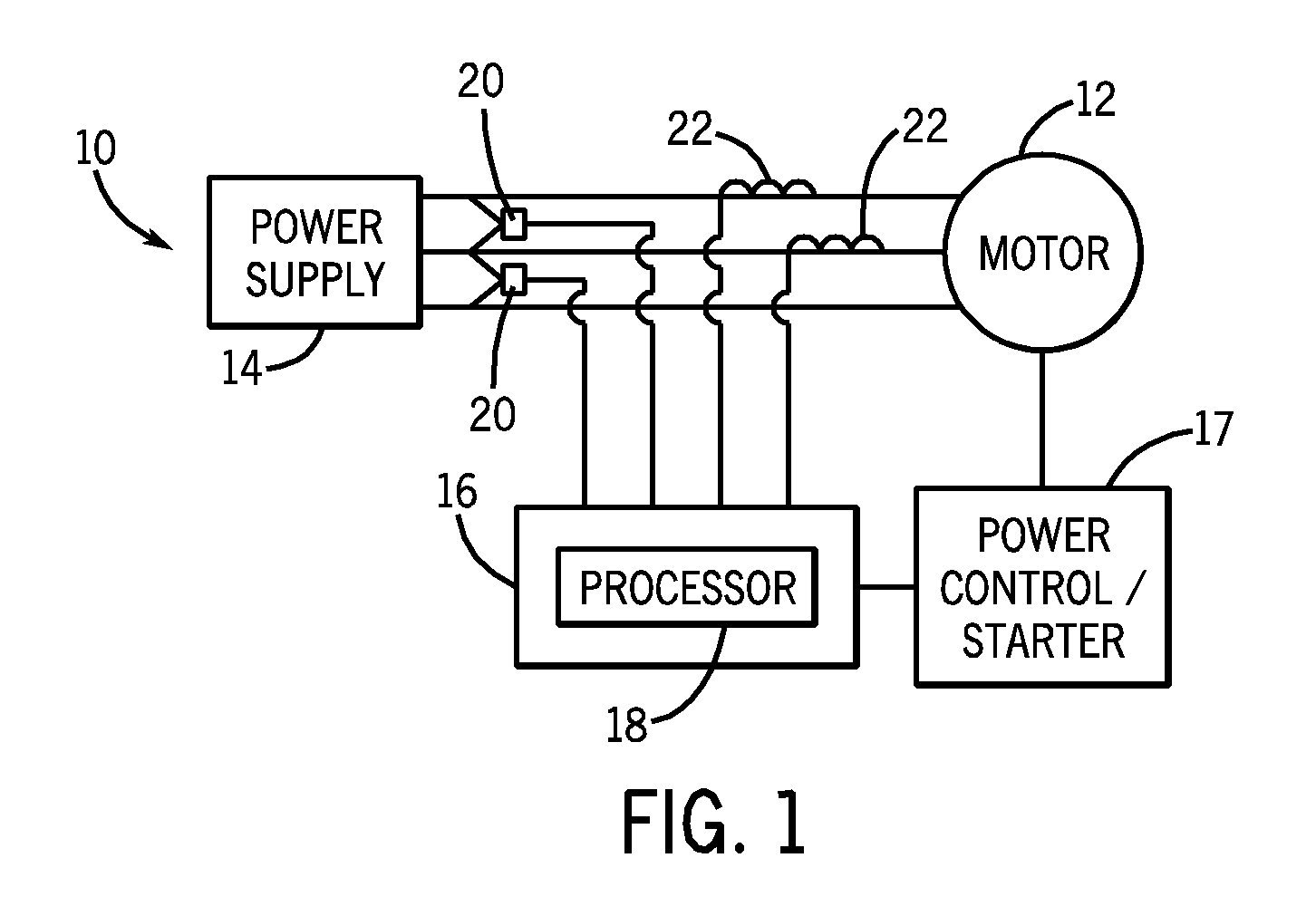
[0020]Referring to FIG. 1, a block diagram of a system incorporating the present invention is shown. The system 10 includes a motor 12 that receives power from a power supply 14. The system 10 also includes a relay assembly 16 used to monitor as well as control operation of the motor in response to operator inputs or motor fault conditions. The motor 12 and the relay assembly 16 typically are coupled to electronic devices such as a power controller and / or a starter 17. The controller / starter 17 is connected to the motor 12. It is contemplated, however, that the power controller / starter may be connected in series between the power supply 14 and the motor 12. In a three-phase system, as shown in FIG. 1, the relay assembly 16 includes a processor 18 that, as will be described in greater detail with respect to FIGS. 2-5, determines motor efficiency while the motor 12 is in operation (i.e., operating online). Though the processor 18 is depicted as being included in the relay assembly 16,...


PUM


Abstract

A system and method for nonintrusively determining electric motor efficiency includes a processor programmed to, while the motor is in operation, determine a plurality of stator input currents, electrical input data, a rotor speed, a value of stator resistance, and an efficiency of the motor based on the determined rotor speed, the value of stator resistance, the plurality of stator input currents, and the electrical input data. The determination of the rotor speed is based on one of the input power and the plurality of stator input currents. The determination of the value of the stator resistance is based on at least one of a horsepower rating and a combination of the plurality of stator input currents and the electrical input data. The electrical input data includes at least one of an input power and a plurality of stator input voltages.

Description

CROSS-REFERENCE TO RELATED APPLICATION[0001]This application claims the benefit of both prior U.S. Provisional Application Ser. No. 60 / 932,741 filed Jun. 4, 2007 and of prior U.S. Provisional Application Ser. No. 60 / 959,459 filed Jul. 13, 2007.GOVERNMENT LICENSE RIGHTS[0002]The present invention was made at least in part with Government support under Contract No. DE-FC36-04GO14000, awarded by the United States Department of Energy. The Government may have certain rights in the invention.BACKGROUND OF THE INVENTION[0003]The invention relates generally to the determination of an electric motor's operating efficiency while the motor is running without the need for any additional sensors, other than standard current and voltage sensors on the input side of the motor.[0004]Motor-driven systems are generally believed to use a majority of the total electric energy produced. Of the total number of motor-driven systems in use, only a small fraction have their efficiency and health monitored....

Claims


Application Information

Patent Timeline
IPC IPC(8): G01R31/34
CPCH02P23/14G01R31/343
Inventor LU, BINHABETLER, THOMAS G.HARLEY, RONALD G.
Owner EATON CORP
Why Eureka
Try Eureka