
Engine event-based correction of engine speed fluctuations

a technology of engine speed and event, which is applied in the direction of machines/engines, electrical control, instruments, etc., can solve the problems of undesirable oxygen sensors and other devices may not have acquired enough information to provide adequate feedback control, and may not be able to provide accurate information, so as to reduce hydrocarbon emissions from vehicles and engine roughness during initial operation

Active Publication Date: 2008-12-11
FCA US
View PDF22 Cites 9 Cited by
  • Summary
  • Abstract
  • Description
  • Claims
  • Application Information

AI Technical Summary

Benefits of technology

The patent describes a method for controlling the ignition timing of a combustion engine by measuring the roughness of its operation and adjusting the ignition timing to bring it within a certain threshold. This allows for discrete changes in ignition timing, such as in individual cylinder combustion events, to achieve better engine performance while reducing emissions. The method can also be used to maintain a relatively smooth engine operation during initial start-up after a cold start.

Problems solved by technology

Also, in the period immediately following an engine start, the oxygen sensor and other devices may not have acquired enough information to provide adequate feedback control.
Therefore, for a period of time immediately following a cold start up of the vehicle engine, the oxygen sensor may not be capable of providing accurate information with which the engine may be controlled.
As a consequence, undesirable hydrocarbon emissions may be emitted from the vehicle within the period immediately following start-up of the engine.
Additionally, immediately following a cold engine start, the catalyst of a catalytic converter can be ineffective since the catalyst may require a period of time to warm up to a temperature at which the catalyst can operate effectively.
As a consequence, hydrocarbon emissions may be even higher during initial engine operation, especially after a cold start.

Method used


Image

  • Engine event-based correction of engine speed fluctuations
  • Engine event-based correction of engine speed fluctuations
  • Engine event-based correction of engine speed fluctuations

Examples


Embodiment Construction

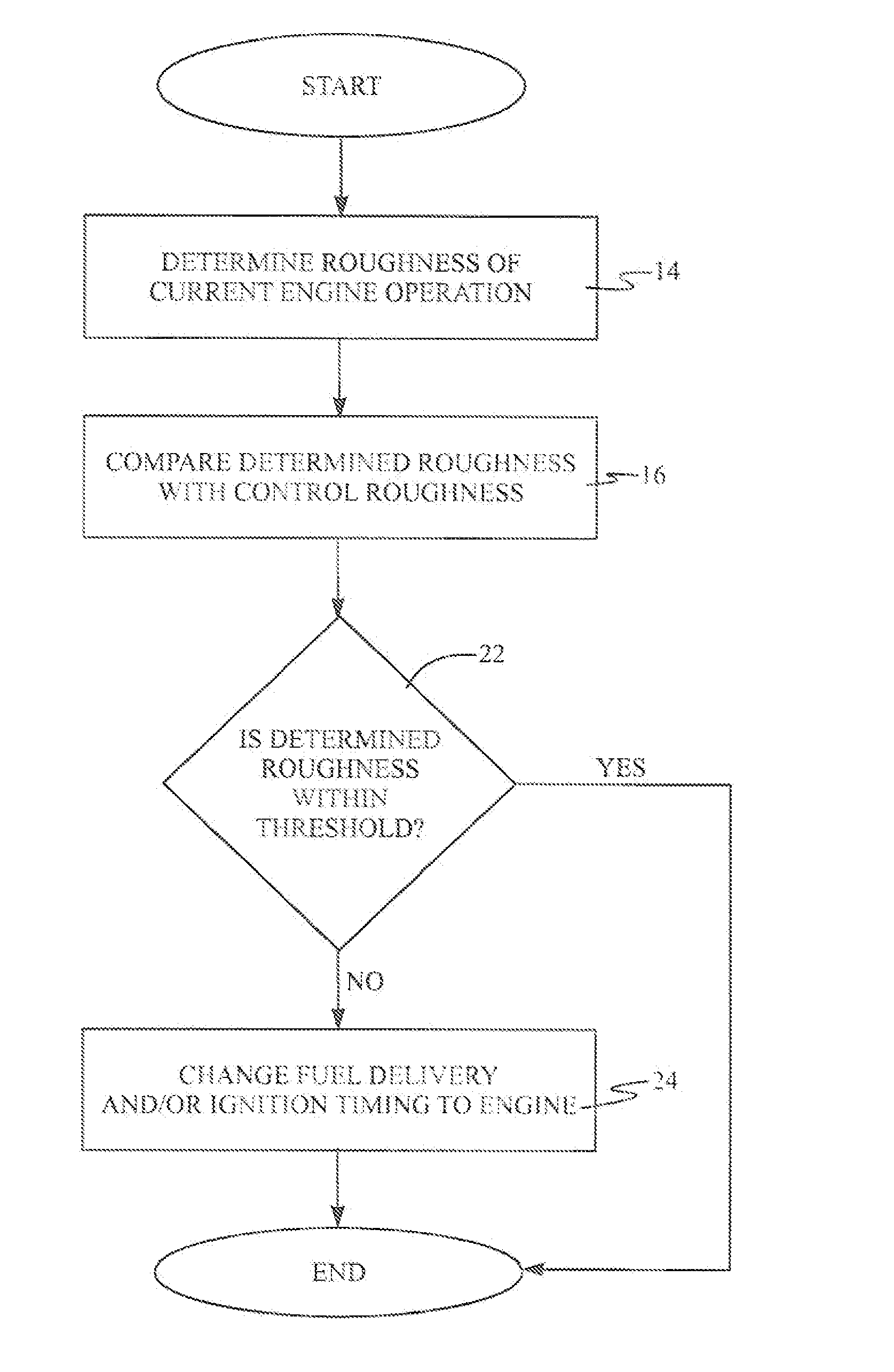
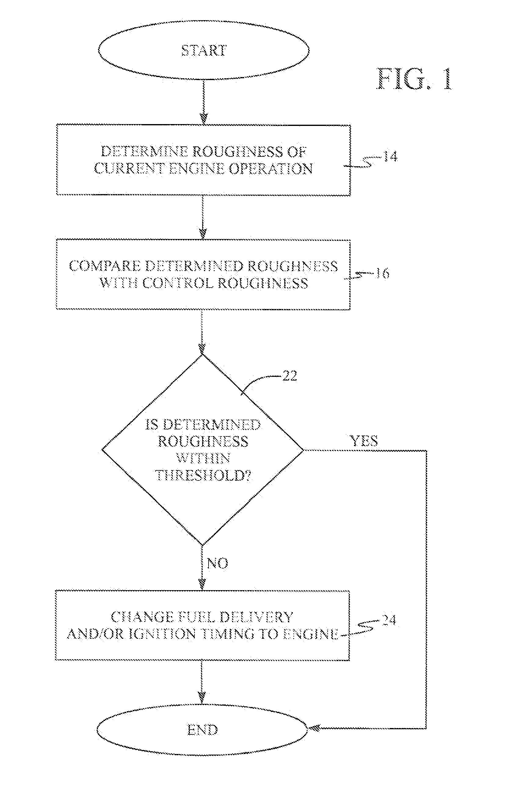
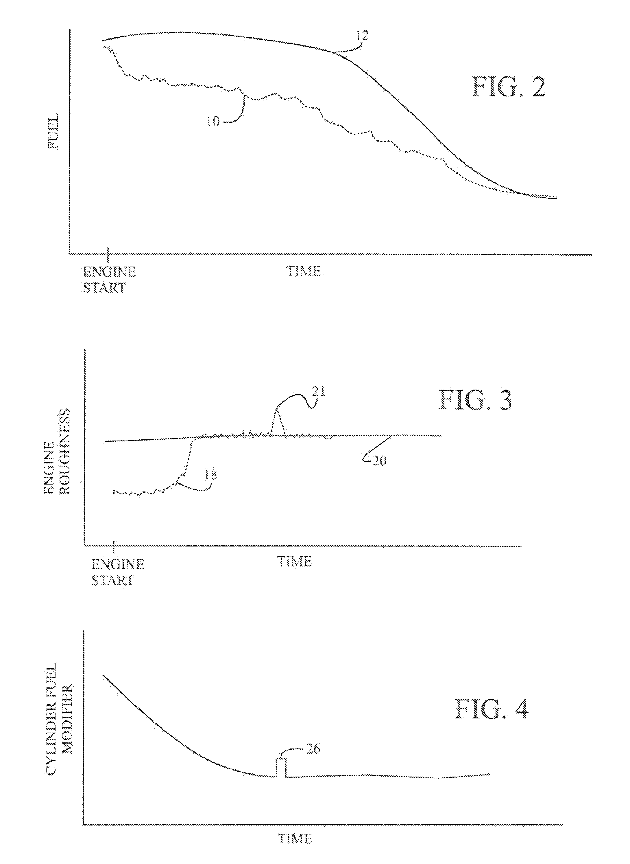
[0015]Referring in more detail to the drawings, FIG. 1 generally illustrates a process by which an engine fuel injection event and / or engine ignition timing event can be modified as a function of current engine operation. In one presently preferred implementation, the process is employed during initial cold start of an engine, although the process may be employed otherwise during operation of the engine, including after a hot start, or otherwise as desired. Vehicles can emit a substantial amount of hydrocarbons to the atmosphere during initial engine operation. Accordingly, in at least some engines and in some engine applications, it may be desirable to provide a relatively lean fuel and air mixture into the engine cylinders for combustion. The relatively lean fuel and air mixture may contain less fuel than a stoichiometric value for combustion as shown in FIG. 2 where line 10 represents a desired lean mixture and line 12 represents a stoichiometric mixture. However, if the fuel and...


PUM


Abstract

Ignition timing for a combustion engine may be controlled by determining the roughness of current engine operation, comparing the determined roughness with a control roughness to determine if the determined roughness is within a threshold limit of the control roughness, and changing the ignition timing in a subsequent fuel delivery event as a function of the difference between the determined roughness and the control roughness. Preferably, the ignition timing is changed at least when the determined roughness is not within the threshold limit, although other factors may be taken into account when changing the ignition timing.

Description

FIELD OF THE INVENTION[0001]The present invention relates generally to internal combustion engines and more particularly to correction of engine speed fluctuations.BACKGROUND OF THE INVENTION[0002]Automotive vehicles may employ a fuel injected internal combustion engine in which a fuel injector discharges fuel into air in an intake manifold or combustion chamber of the engine and a spark plug ignites the fuel and air in the combustion chamber. The conventional fuel injector typically is controlled and responds to a fuel injection pulse width signal, which determines an amount of fuel injected. The fuel injection pulse width signal can be implemented to follow a programmed curve or algorithm, which is generally utilized to provide adequate engine performance when feedback or closed-loop engine control is not available. Similarly, the conventional spark plug typically is controlled and responds to an ignition timing signal that determines when the spark plug is activated. The ignition...

Claims


Application Information

Patent Timeline
Patent Type & Authority Applications(United States)
IPC IPC(8): F02P5/00
CPCF02D37/02F02D41/062F02D41/1498F02P5/1555Y02T10/46Y02T10/40
Inventor DEGROOT, KENNETH P.WUTTKE, JEFFREY P.KENNIE, GERALD LEEFETT, DENNIS W.
Owner FCA US
Learn More