Varying mugfet width to adjust device characteristics

a technology of mugfet and device characteristics, applied in the field of multi-gate transistors, can solve the problems of cost and performance shortcomings of conventional multi-gate approaches

Inactive Publication Date: 2008-12-11
TEXAS INSTR INC
View PDF3 Cites 47 Cited by
  • Summary
  • Abstract
  • Description
  • Claims
  • Application Information

AI Technical Summary

Benefits of technology

[0005]The following presents a simplified summary in order to provide a basic understanding of one or more aspects of the invention. This summary presents one or more concepts of the invention in a simplified form as a prelude to the more deta...

Problems solved by technology

In practice, however, the conventional multi-gate appr...

Method used


Image

  • Varying mugfet width to adjust device characteristics
  • Varying mugfet width to adjust device characteristics
  • Varying mugfet width to adjust device characteristics

Examples


Embodiment Construction

[0015]The present invention will now be described with reference to the attached drawing figures, wherein like reference numerals are used to refer to like elements throughout, and wherein the illustrated structures and devices are not necessarily drawn to scale.

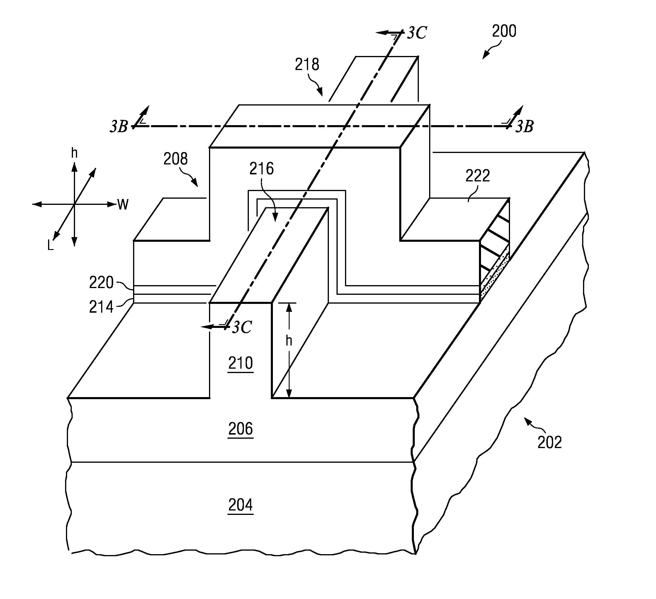
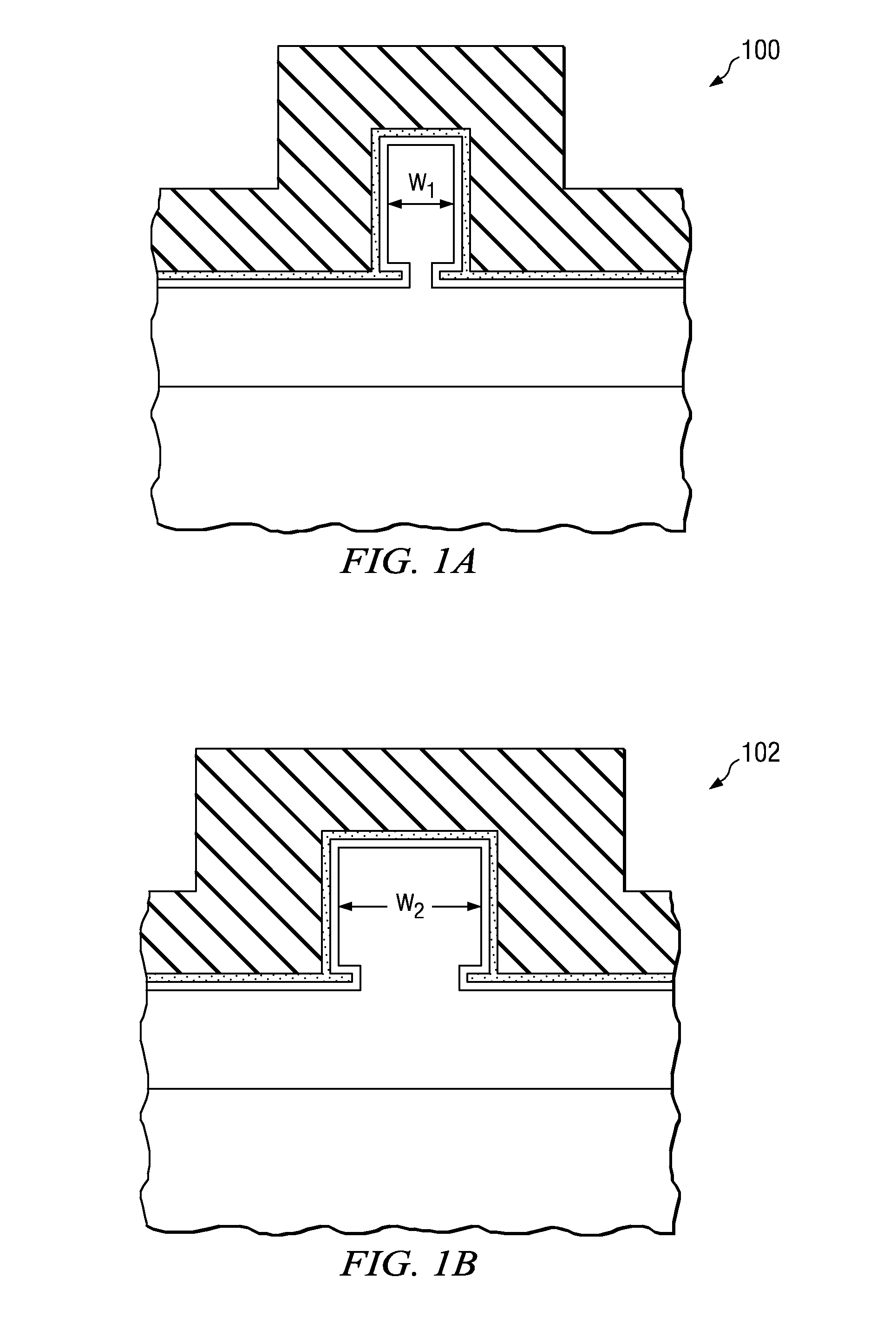
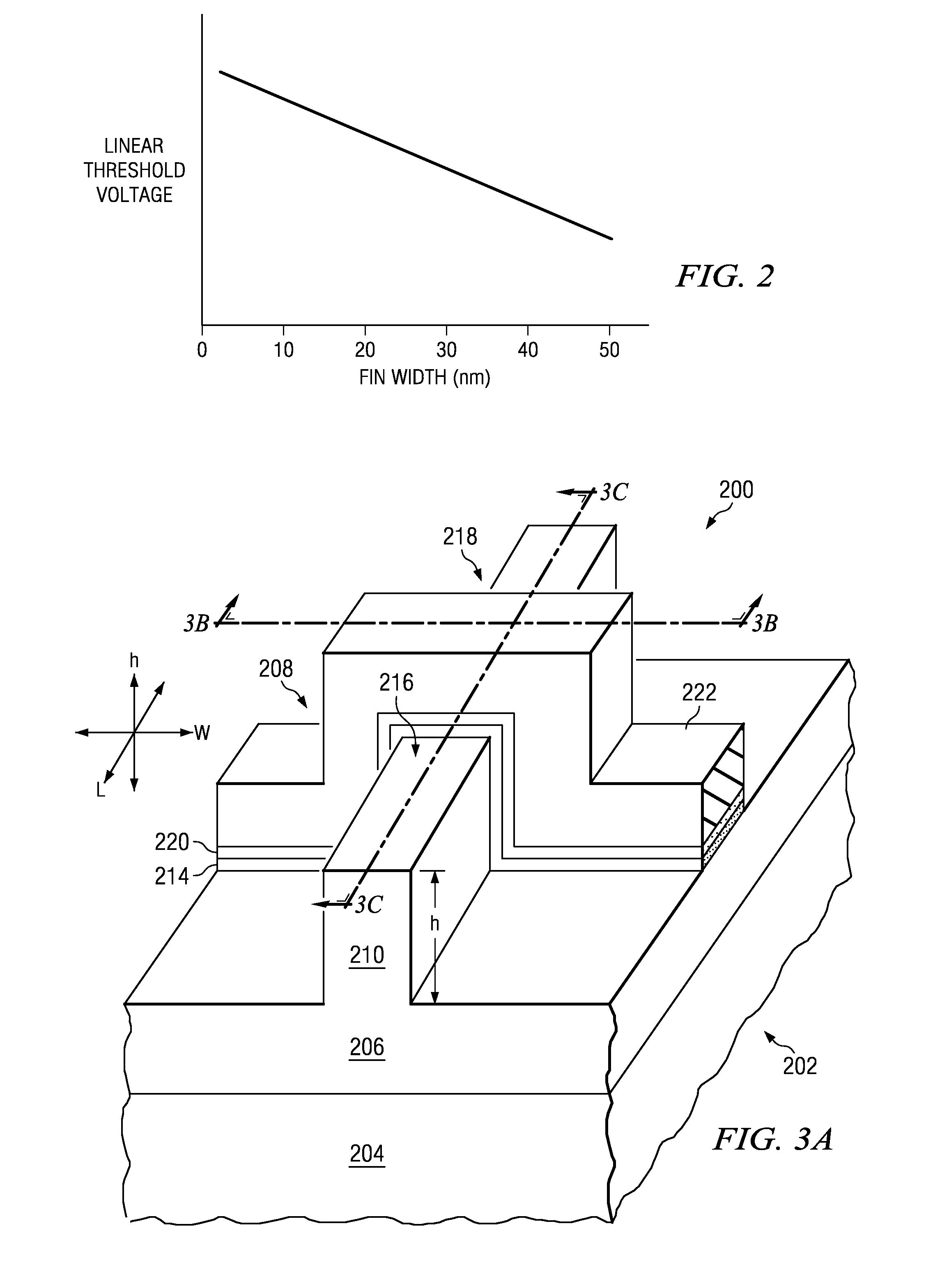
[0016]One concept of the invention allows a designer to tailor a MuGFET's voltage threshold (VT) where strong inversion occurs as a function of the MuGFET's fin width (W). Thus, an integrated circuit may be provided that has MuGFETs of varying fin widths, where MuGFETs with narrower fins have higher VT's and MuGFETs with wider fins have lower VT's. For example, FIG. 1A shows a first (relatively narrow) MuGFET 100, having fin width W1 and voltage threshold VT1, and FIG. 1B shows a second (relatively wide) MuGFET 102 having fin width W2 and voltage threshold VT2. As shown W2>W1, and therefore VT1>VT2. Other than their differing fin widths and voltage thresholds, the MuGFETs 100, 102 may have many, if not all, of the same or si...


PUM


Abstract

One embodiment of the present invention relates to an integrated circuit that includes a first multi-gate transistor that has a first fin width and a first threshold voltage. The integrated circuit also includes a second multi-gate transistor that has a second fin width that is greater than the first width and a second threshold voltage that is less than the first threshold voltage. Other circuits and methods are also disclosed.

Description

FIELD OF INVENTION[0001]The present invention relates generally to semiconductor devices and more particularly to multi-gate transistors (MuGFETs).BACKGROUND OF THE INVENTION[0002]As the performance and process limitations on scaling planar transistors are reached, attention has been recently directed to transistor designs having multiple gates (e.g., three-dimensional MOS transistors), which may also be referred to as Multi-Gate Field Effect Transistors (MuGFETs). In theory, these designs provide more control over a scaled channel by situating the gate around two or more sides of a silicon fin in which a conductive channel is formed.[0003]By alleviating the short channel effects seen in traditional scaled planar transistors, multi-gate designs offer the prospect of improved transistor performance. This is due primarily to the ability to invert a larger portion of the channel silicon because the gate extends on more than one side of the channel. In practice, however, the conventiona...

Claims


Application Information

Patent Timeline
IPC IPC(8): H01L29/76H01L21/8234
CPCH01L21/845H01L27/1211H01L29/785H01L2029/7857
Inventor XIONG, WEIZECLEAVELIN, CLOVES RINN
Owner TEXAS INSTR INC
Why Eureka
Try Eureka