Imaging apparatus, imaging method, integrated circuit, and storage medium

a technology which is applied in the field of imaging apparatus and integrated circuit, can solve the problems of slowing down the shutter speed and obtaining a sufficient amount of light, and increasing the depth of field, so as to achieve large luminance and high luminance

Active Publication Date: 2008-10-23
PANASONIC INTELLECTUAL PROPERTY CORP OF AMERICA
View PDF13 Cites 88 Cited by
  • Summary
  • Abstract
  • Description
  • Claims
  • Application Information

AI Technical Summary

Benefits of technology

[0081]The present invention provides an imaging apparatus, an imaging method, a computer-readable storage medium that stores a program, and an integrated circuit for appropriately capturing an image of even a s...

Problems solved by technology

Also, users may often set a slower shutter speed and a smaller aperture and increase the depth of field.
When capturing an image of a dark scene, however, the imaging apparatus is required to maximize the aperture and slow the shutter speed to obtain a sufficiently large amount of light.
Such movement of the imaging apparatus or the subject may blur images.
In this case, when capturing an image of a scene (subject) that h...

Method used


Image

  • Imaging apparatus, imaging method, integrated circuit, and storage medium
  • Imaging apparatus, imaging method, integrated circuit, and storage medium
  • Imaging apparatus, imaging method, integrated circuit, and storage medium

Examples


first embodiment

1.1 Structure of the Imaging Apparatus

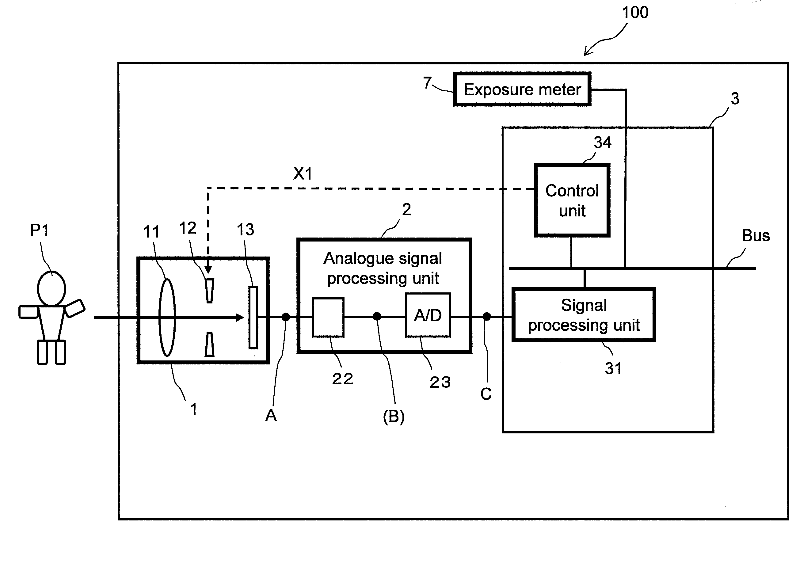
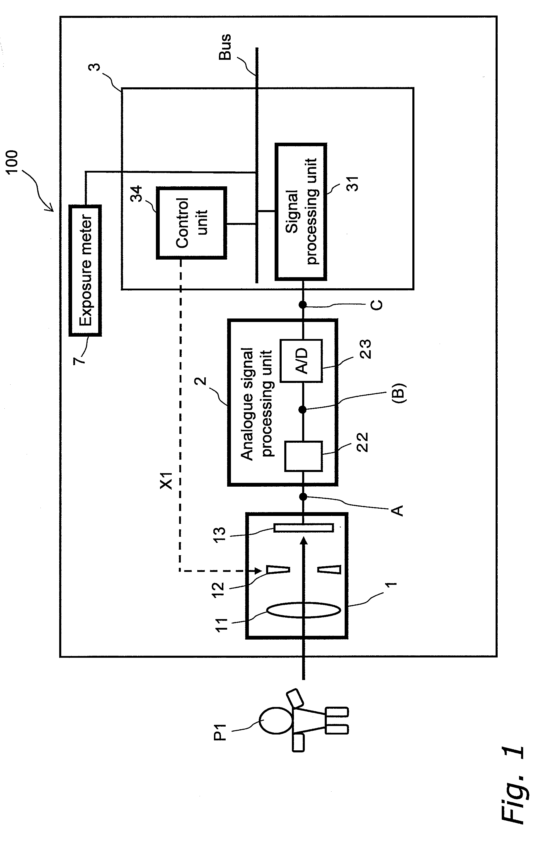
[0130]FIG. 1 shows the structure of an imaging apparatus 100.

[0131]The imaging apparatus 100 includes an optical system 1, an analogue signal processing unit 2, a digital signal processing unit 3, and an exposure meter 7.

[0132]The optical system 1 includes an imaging lens 11, an aperture 12, and an imaging unit 13. The imaging lens 11 focuses light from a subject P1. The aperture 12 adjusts the amount of reflection light from the subject P1, which has been focused through the imaging lens 11. The imaging unit 13 outputs an image signal A according to the adjusted light amount (light amount adjusted by the aperture 12) and the light accumulation time.

[0133]The analogue signal processing unit 2 includes a correlated double sampling (CDS) circuit 21 and an analogue-to-digital (A / D) converter 23.

[0134]The A / D converter 23 converts analogue image (video) signals to 12-bit digital image (video) signals (signals C) corresponding to pixels having levels...

first modification

[0174]The first embodiment describes the case in which the dynamic-range compression conversion characteristics L0 to Lmax are selected according to the preset aperture amount (exposure light amount). Alternatively, the dynamic-range compression unit 2001 may select the dynamic-range compression characteristic Ln according to a maximum value of signals D corresponding to the entire image (first modification).

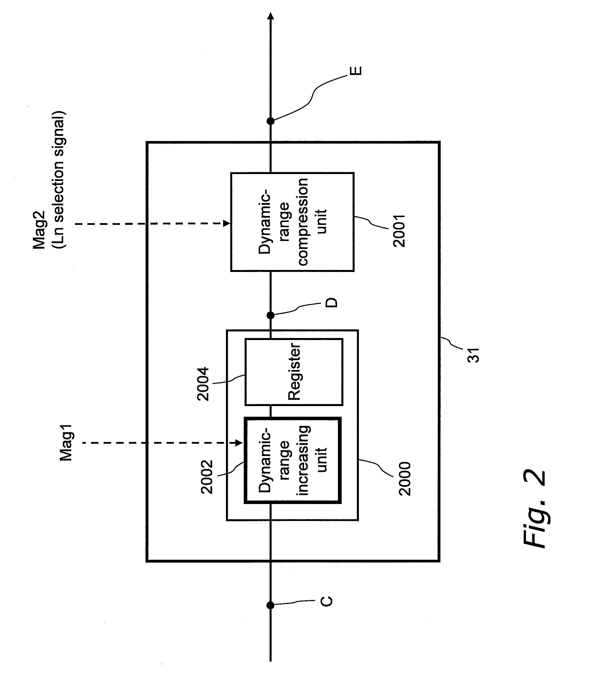
[0175]FIG. 8 shows the structure of a signal processing unit 31′ according to the first modification. In FIG. 8, the processing units that are the same as the units described in the first embodiment are given the same reference numerals as those components. The signal processing unit 31′ according to the first modification differs from the signal processing unit 31 shown in FIG. 2 only in its parameter determination unit 800.

[0176]The parameter determination unit 800 includes a peak detection unit 802.

[0177]The peak detection unit 802 receives signals D corresponding to one imag...

second modification

[0185]Alternatively, the aperture amount of the aperture 12 and the dynamic range increase 10 ratio may be set according to the peak value of the entire image that is detected by the parameter determination unit 800 of the first modification (second modification).

[0186]The structure according to the first modification uses the aperture value of the aperture 12 preset by a separate means (for example, ¼). In that case, signals A corresponding to the brightest portion of the scene 201 stored in the imaging unit 13 (output from the imaging unit 13) do not have a value as high as the maximum dynamic range of 150% (signals only have a value of up to 125%). In this case, digital signals C obtained for the scene at the imaging timing do not have values as high as the maximum input dynamic range (quantization resolution) of the A / D conversion. Thus, the structure according to the first modification fails to effectively use the maximum input dynamic range (quantization resolution).

[0187]The ...


PUM


Abstract

An imaging apparatus appropriately captures a large dynamic range image of even a scene including a backlit person with a blue sky background in a manner that the person's face has an appropriate luminance level without saturating the background sky. In the imaging apparatus, an imaging unit obtains analogue image signals through exposure control that prevents a highlight from being saturated, an A/D converter converts the analogue image signals to digital image signals, and a signal processing unit linearly increases the dynamic range of the digital image signals. The image signals with the increased dynamic range are nonlinearly compressed to have a dynamic range of 100% or less through nonlinear dynamic range compression that intensively compresses a highlight portion. The imaging apparatus with this structure first increases the dynamic range of an image and efficiently compresses the increased large dynamic range of the image.

Description

BACKGROUND OF THE INVENTION[0001]1. Field of the Invention[0002]The present invention relates to an imaging apparatus and an integrated circuit that functions as an imaging apparatus, and more particularly, to an imaging apparatus that appropriately captures an image of a scene (subject) having a large dynamic range, an integrated circuit that functions as such an imaging apparatus, and a computer-readable storage medium that stores a program used in such an imaging apparatus.[0003]2. Description of the Related Art[0004]Imaging apparatuses, such as a digital still camera for capturing still images and a digital video camera for capturing moving images, capture images in the following manner. In an imaging apparatus, an optical system focuses light and forms an image through exposure control, and a solid-state image sensor, such as a CCD (charge-coupled device) image sensor or a CMOS (complementary metal oxide semiconductor) image sensor, converts the image to electric signals, which...

Claims


Application Information

Patent Timeline
IPC IPC(8): H04N5/235
CPCH04N5/2351H04N5/2352H04N5/2355H04N23/72H04N23/71H04N23/741
Inventor YAMASHITA, HARUOITO, TAKESHISATO, DAISUKE
Owner PANASONIC INTELLECTUAL PROPERTY CORP OF AMERICA
Why Eureka
Try Eureka