Methods and apparatus for mapping control channels to resources in OFDM systems

a control channel and resource technology, applied in the field of transmitting data, can solve problems such as increasing decoding complexity at the receiver

Active Publication Date: 2008-12-11
SAMSUNG ELECTRONICS CO LTD
View PDF7 Cites 58 Cited by
  • Summary
  • Abstract
  • Description
  • Claims
  • Application Information

AI Technical Summary

Benefits of technology

[0008]It is therefore an object of the present invention to provid

Problems solved by technology

The method of blind decoding, however, inevitabl

Method used


Image

  • Methods and apparatus for mapping control channels to resources in OFDM systems
  • Methods and apparatus for mapping control channels to resources in OFDM systems
  • Methods and apparatus for mapping control channels to resources in OFDM systems

Examples


first embodiment

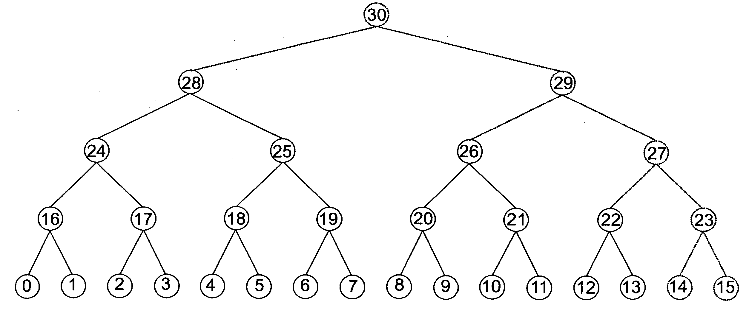
[0065]In a first embodiment according to the principles of the present invention, a graph with multiple rooted trees is constructed with at least one leaf node representing one resource element that may be allocated for control channel transmission, and at least one inner node or root node representing the set of resource elements that may be allocated for control channel transmission, the set of resource elements being represented by the leaf nodes that are descendants of the inner node or the root node. These trees are used in resource allocation and blind decoding of the control channels. As an example, in FIG. 12, the leaf nodes are indexed from 0 to 13. Using a binary tree construction, we can construct a graph with three rooted binary trees as shown in FIG. 12A. The three trees are tree 310 with Node 24 as a root node, tree 311 with Node 23 as a root node, and tree 312 with Node 20 as a root node. Each leaf node corresponds to a physical control channel element (CCE), i.e., a ...

second embodiment

[0067]In a second embodiment according to the principles of the invention, a graph with one rooted tree is constructed where at least one leaf node represents one resource element and at least at least one leaf node does not represent any resource element. For example, we can construct one binary tree as shown in FIG. 12B with Node 30 as its root node. Note that in this tree, there is no resource element corresponding to either one of Nodes 14, 15, and 23. Similarly, some of the leaf nodes below Nodes 27, 29, and 30 have no resource elements corresponding to them. Preferably, Nodes 14, 15, and 23 can be reserved or be used to indicate either no resource allocation or some other purpose. Nodes 27, 29, and 30, however, can still be used. For example, a resource allocation with Node 29 to a control channel may mean the physical CCEs that represented by node 8, 9, 10, 11, 12, 13 are used for that control channel.

[0068]It is assumed that there is a control channel element indexing scheme...

third embodiment

[0071]In a third embodiment according to the principles of the present invention, the mapping from resource elements to tree nodes may be cell-specific or change over time. For example, in FIG. 12A, the leaf Node 3 may represent CCE 3 in one subframe and represent CCE in another subframe. Also, at the same time instant, the leaf Node 3 may represent CCE 4 in a first cell and represent CCE 9 in a second cell. Different mapping over time and across cells is beneficial in randomize the interference over time and across cells. It is also possible that the mapping from resource elements to tree nodes is differently for different UEs, as long as the base station can resolve the possible conflict between different mappings.


PUM


Abstract

A method for data transmission. The method including the steps of generating at least one resource tree, mapping a plurality of resource elements into respective leaf nodes in the at least one resource tree according to a certain mapping scheme, with each node in the at least one resource tree representing a resource allocation scheme for data transmission, and transmitting data using a resource allocation scheme selected from among the plurality of resource allocation schemes represented by respective nodes in the at least one resource tree. In response to reception of the data, a receiver decodes the data by recursively applying the plurality of resource allocation schemes represented by respective nodes in the at least one resource tree until the data is decoded.

Description

CLAIM OF PRIORITY[0001]This application makes reference to, incorporates the same herein, and claims all benefits accruing under 35 U.S.C. §119 from provisional applications earlier filed in the U.S. Patent & Trademark Office on 8 Jun. 2007 and there duly assigned Ser. No. 60 / 929,024, and on 22 Jun. 2007 and there duly assigned Ser. No. 60 / 929,351, respectively.BACKGROUND OF THE INVENTION[0002]1. Field of the Invention[0003]The present invention relates to a method for transmitting data, and more specifically, a method for transmitting data by using resource elements stored in at least one resource trees.[0004]2. Description of the Related Art[0005]Telecommunication enables transmission of data over a distance for the purpose of communication between a transmitter and a receiver. The data is usually carried by radio waves and is transmitted using a limited transmission resource. That is, radio waves are transmitted over a period of time using a limited frequency range.[0006]Usually,...

Claims


Application Information

Patent Timeline
IPC IPC(8): H04L27/28
CPCH04B7/0417H04B7/0452H04L5/0032H04B7/0634H04W72/00H04B7/0632
Inventor PI, ZHOUYUE
Owner SAMSUNG ELECTRONICS CO LTD
Why Eureka
Try Eureka