Pull-style tensioner system for a top-tensioned riser

a tensioner system and tensioner technology, applied in the direction of sealing/packing, drilling pipes, drilling/well accessories, etc., can solve the problems of increasing the pressure of the cylinder to stroke in and out, increasing the tension of the riser, and increasing the tension of the cylinder

Active Publication Date: 2008-12-11
TECH FRANCE SA
View PDF9 Cites 46 Cited by
  • Summary
  • Abstract
  • Description
  • Claims
  • Application Information

AI Technical Summary

Benefits of technology

[0016]Hydro-pneumatic retraction of the tensioner rods in response to platform motion applies an upward tension force to the support conductor coupling assembly. Axial tension loads are thereby conveyed from the tensioners to the ...

Problems solved by technology

Platform responses to environmental conditions, mainly heave and horizontal motions causing hull set-down, necessitate changes in riser length relative to the platform, which causes the tensioning cylinders to stroke in and out.
However, when the platform takes a significant horizontal offset, the compression of the gas in the cylinders causes increased cylinder pressure and thus increased riser tension.
Also, riser vortex induced vibration (VIV) oscillations can be transferred across the tension ring and into the upper riser stem joint, possibly affecting its fatigue life.
If a tension cylinder failure occurs, the eccentric load generated by the unequal application of cylinder forces at the tension ring may also cause additional bending moments that must be reacted to by the riser pipe.
The unbalanced cylinder forces can also cause the riser and the surface tree to lean to one side.
However, because the cylinders are generally hung from above to pull up and are also angled inboard to the riser, failed ...

Method used


Image

  • Pull-style tensioner system for a top-tensioned riser
  • Pull-style tensioner system for a top-tensioned riser
  • Pull-style tensioner system for a top-tensioned riser

Examples


Embodiment Construction

[0028]As used herein, the terms “invention” and “present invention” are to be understood as encompassing the invention described herein in its various embodiments and aspects, as well as any equivalents that may suggest themselves to those skilled in the pertinent arts.

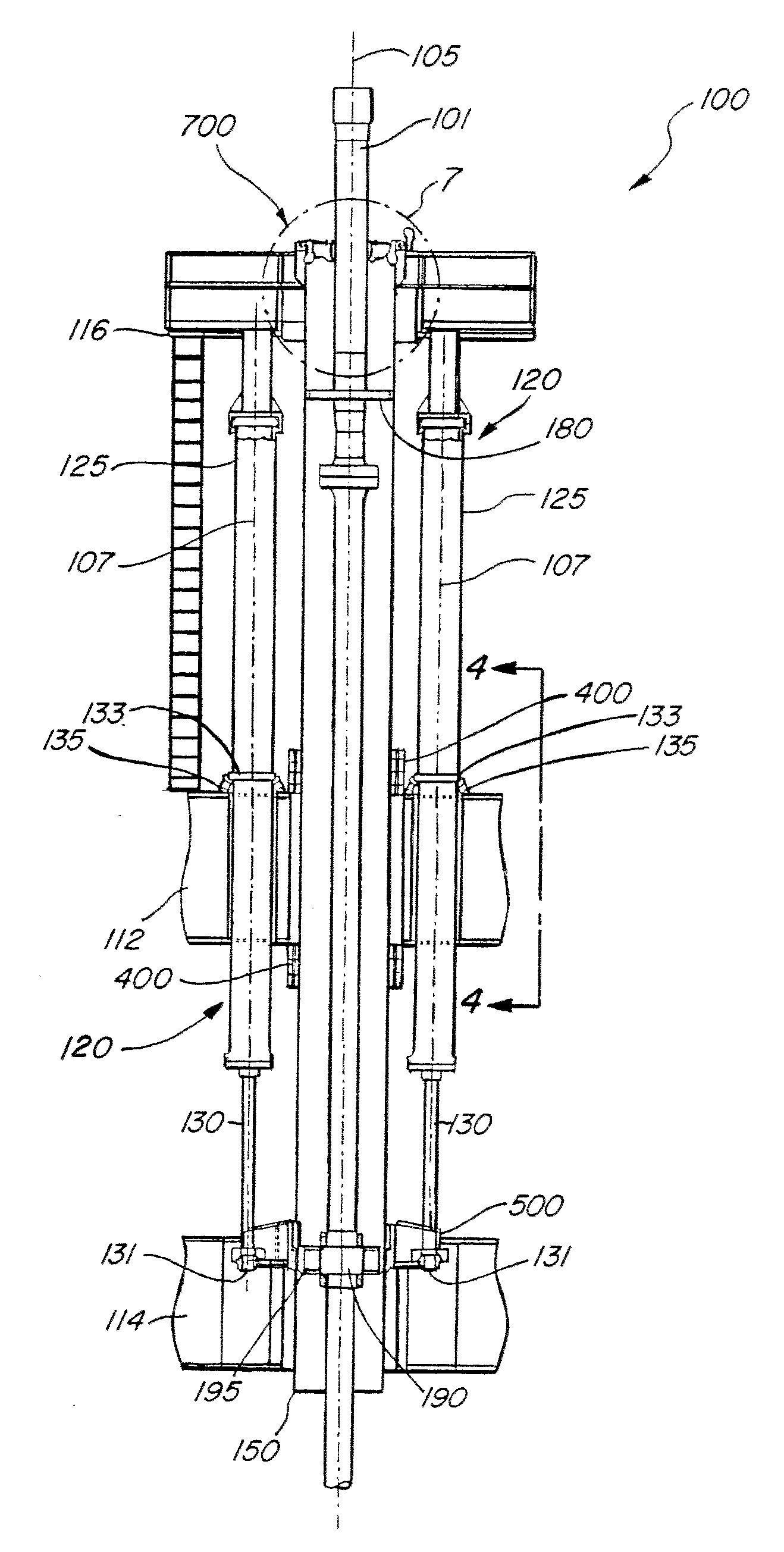
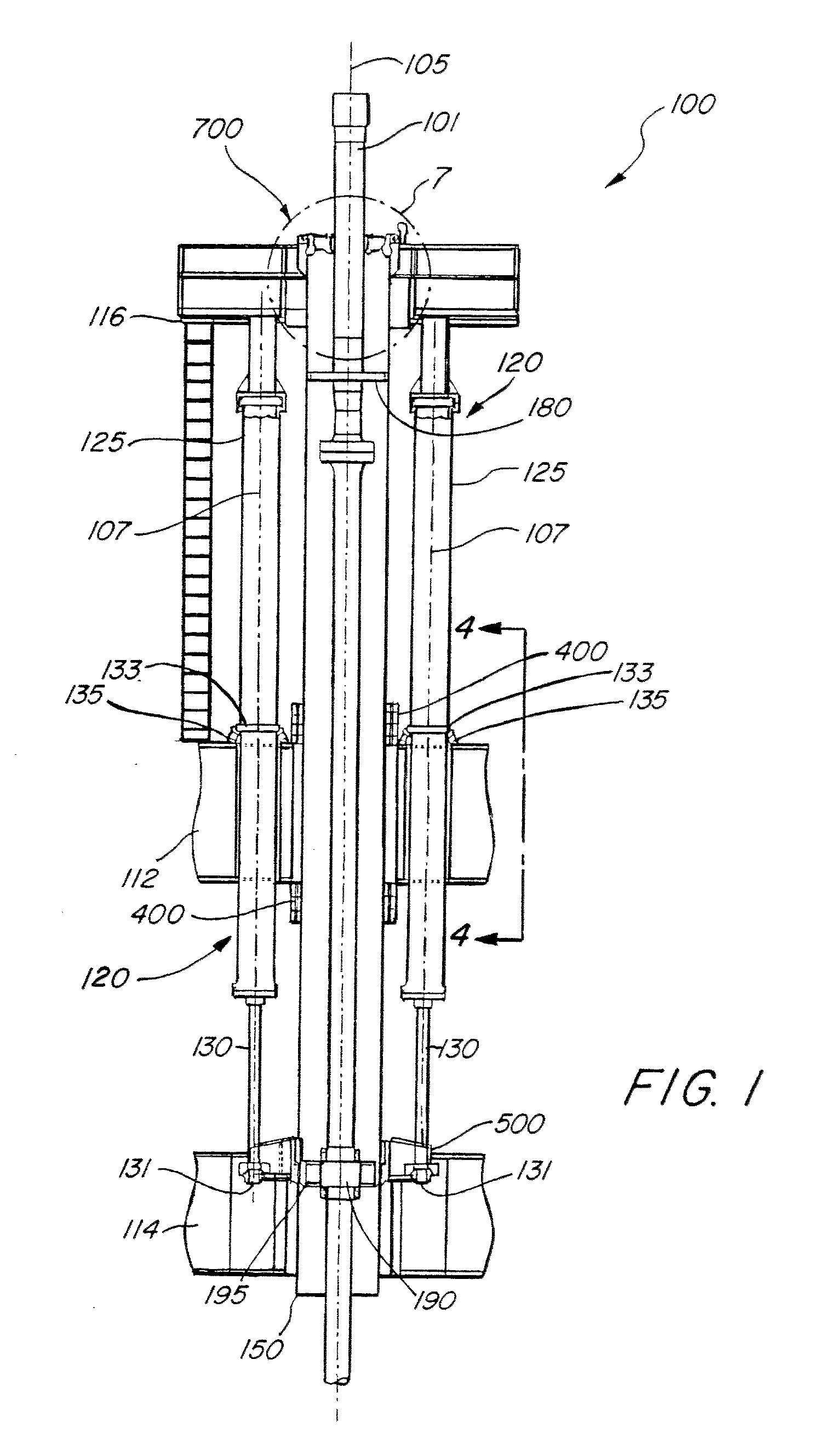
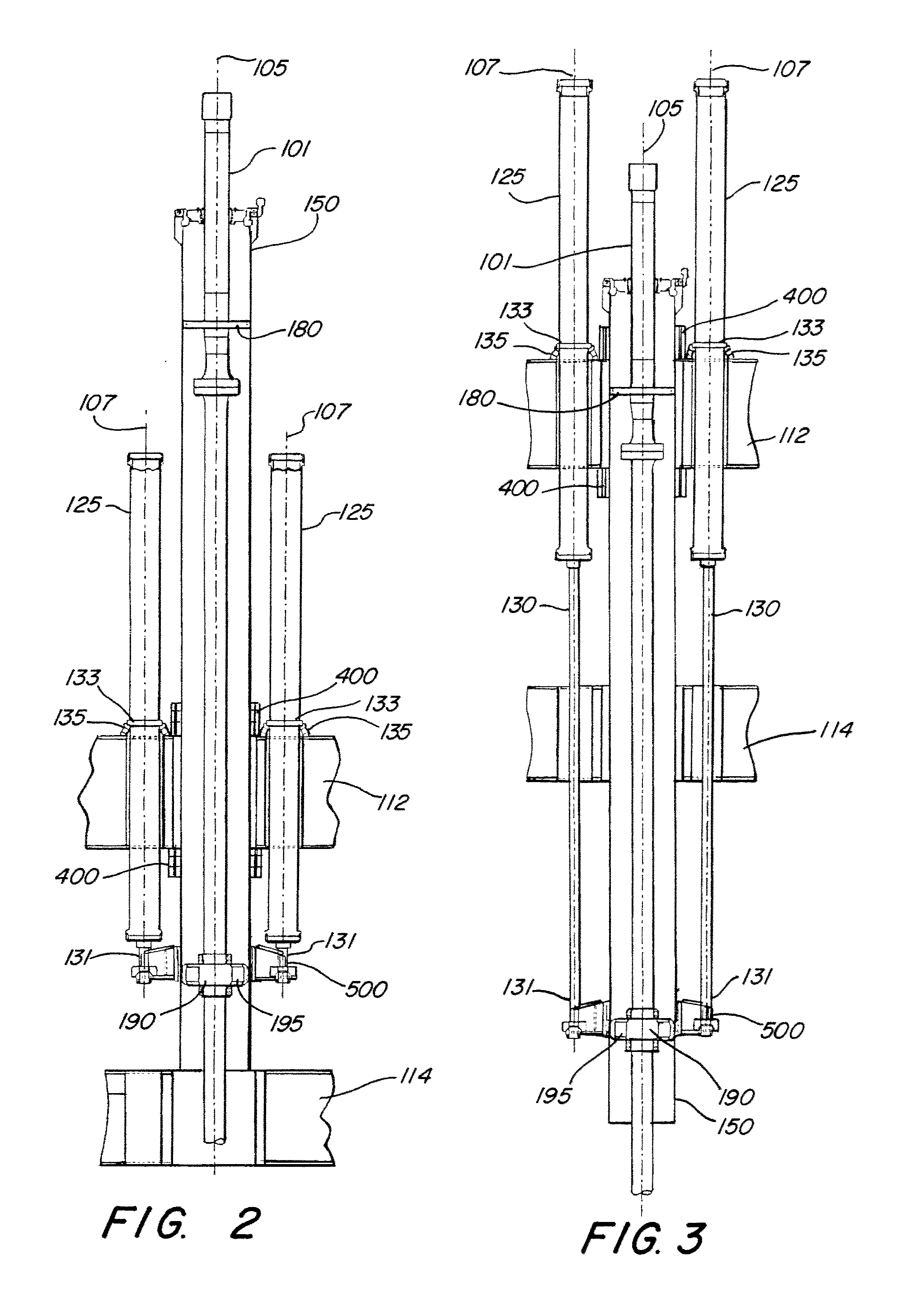
[0029]Referring to the drawings, FIGS. 1-3 illustrate an offshore platform 100 that incorporates a tensioner system in accordance with the present invention. The platform 100 may be for example, a spar-type platform, a tension-leg platform, extended draft platform, or semi-submersible platform, or a floating vessel of the type used for drilling and production of hydrocarbons from subsea deposits (hereinafter, floating platform). The tensioner system of the present invention, as described below, may be suitable for use with an offshore dry tree floating platform, in which drilling and production equipment is disposed above the waterline. The drilling and production equipment accesses the hydrocarbon reservoir using at ...


PUM


Abstract

A tensioner system for a top-tensioned riser in a floating platform includes a hydro-pneumatic tensioner assembly resiliently mounted to the floating platform, and a riser support conductor surrounding the riser coaxially, wherein the support conductor conveys a pull-type tensional force from the hydro-pneumatic tensioner assembly to the riser through a riser conductor coupling assembly that engages the tensioner assembly and the riser support conductor to convey the tensional force. A riser tension joint support assembly conveys the tensional force from the riser support conductor to a riser tension joint on the riser. The tensioner assembly compensates for relative platform motion including pitch, heave, and yaw. Also a reactive load assembly is mounted to the platform and reacts to a two-point dynamic bending moment imposed on the riser support conductor, while resisting riser support conductor rotation.

Description

CROSS-REFERENCE TO RELATED APPLICATIONS[0001]Not ApplicableFEDERALLY-SPONSORED RESEARCH OR DEVELOPMENT[0002]Not ApplicableBACKGROUND OF THE INVENTION[0003]This invention relates generally to the field of floating offshore platforms or vessels for the exploitation of undersea deposits of petroleum and natural gas. More specifically, it relates to a system and apparatus for tensioning risers that extend from a subsea wellhead or subsurface structure to a floating platform or vessel.[0004]Offshore platforms for the exploitation of undersea petroleum and natural gas deposits typically support production risers that extend to the platform from one or more wellheads or structures on the seabed. In deep water applications floating platforms (such as spars, tension leg platforms, extended draft platforms, and semi-submersible platforms) are typically used. These platforms are subject to motion due to wind, waves, and currents. Consequently, the risers employed with such platforms must be te...

Claims


Application Information

Patent Timeline
IPC IPC(8): E02D29/00
CPCE21B19/002
Inventor CROTWELL, GERALDYU, ALAN
Owner TECH FRANCE SA
Why Eureka
Try Eureka