
Dual-focus lens and electronic device having the same

a technology of electronic devices and lenses, applied in the field of dual-focus lenses and electronic devices having the same, can solve the problems of increasing the cost of components of driving motors and and achieve the effect of increasing the cost of components of driving motors and increasing the volume of camera modules

Inactive Publication Date: 2008-12-11
POWERGATE OPTICAL INC
View PDF0 Cites 8 Cited by
  • Summary
  • Abstract
  • Description
  • Claims
  • Application Information

AI Technical Summary

Benefits of technology

"The present invention provides a dual-focus lens that can form a clear image in both a long-distance and a short-distance without shifting any lens or rear focus of the lens set. This solves the problem of traditional camera lenses that increase the cost and size of the driving motor and lens. The dual-focus lens includes a stop and at least two lenses, where one of the lenses is relatively close to the stop and has two transmission areas. The lens can form a clear optical image on the same image formation area for both objects at different distances, providing double focus without any active elements or changing the image formation distance. The physical structure of the transmission areas can be selected from a variety of options, such as different thickness areas, curvature areas, or a combination of both. The technical effect of the invention is to provide a compact and cost-effective solution for achieving double focusing without shifting any lens or rear focus."

Problems solved by technology

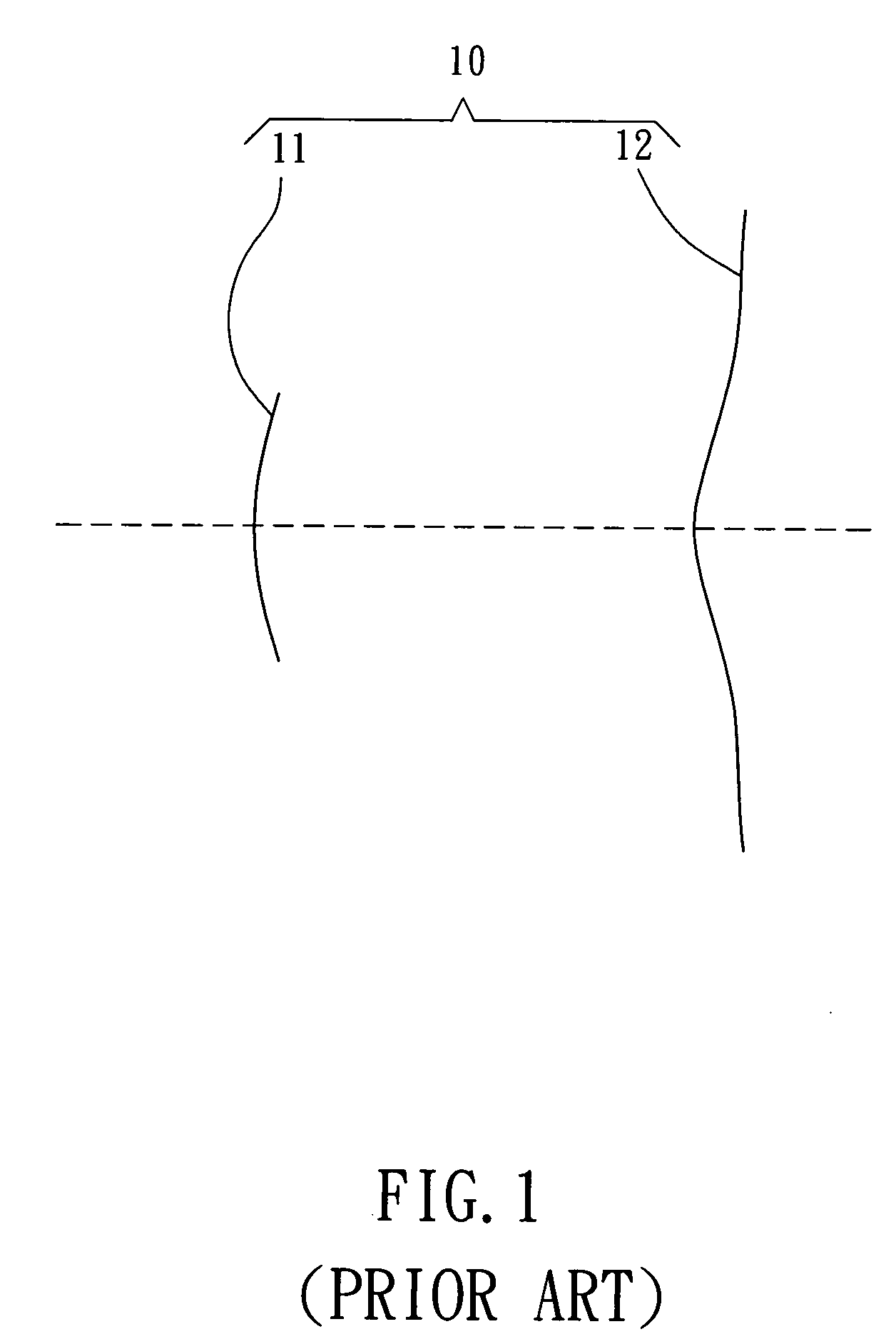
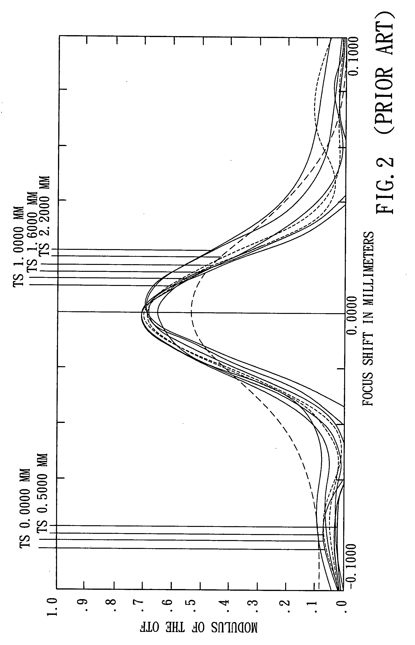
However, most of traditional mobile phones are only provided with a lens having a fixed focus, so that it may only form an unclear image when taking a picture at a short distance (i.e. a micro-distance).
However, the component cost of the driving motor and the entire volume of the camera module will be apparently increased, and therefore leave a room for further improvements.

Method used


Image

  • Dual-focus lens and electronic device having the same
  • Dual-focus lens and electronic device having the same
  • Dual-focus lens and electronic device having the same

Examples


Embodiment Construction

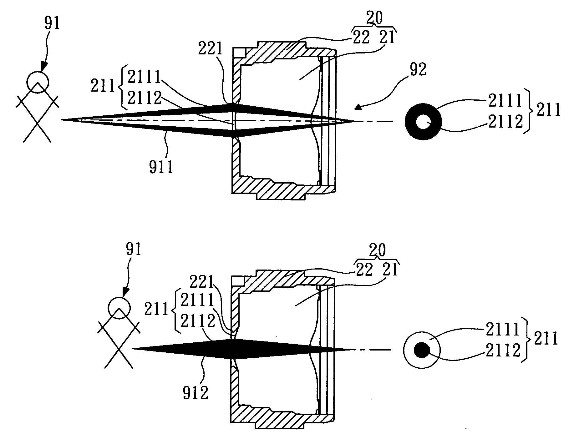
[0027]Referring to FIG. 3, a dual-focus lens 20 according to a preferred embodiment of the present invention is illustrated. As shown, the dual-focus lens 20 comprises a lens set 21 including a plurality of lenses, and a hollow lens base 22 for receiving and positioning the lenses of the lens set 21 therein. The dual-focus lens 20 is used to form a clear optical image of an object 91 on an image formation area 92, wherein the image formation area 92 is preferably an active surface of an image sensor chip for converting the optical image of the object 91 into an electrical signal capable of being recognized by a computer, so as to carry out a function of digital camera. In the preferred embodiment of the present invention, the image sensor chip can be selected from a charge coupled device (CCD) sensor or a complementary metal-oxide semiconductor (CMOS) sensor. Furthermore, because the dual-focus lens 20 of the present invention is advantageous to minimize the entire volume, the dual-...


PUM


Abstract

A dual-focus lens includes a stop and at least two lenses. One of the lenses is relatively close to the stop, and formed with a first transmission area and a second transmission area. When the at least two lenses are fixed without shifting any lens, an image beam reflected from a first object distance can pass through the first transmission area to form a clear optical image on an image formation area located at a fixed position, and an image beam reflected from a second object distance can pass through the second transmission area to form a clear optical image on the same image formation area, so as to achieve a purpose of providing double focuses without any active elements or changing the image formation distance. Physical structures of the first transmission area and the second transmission area can be selected from the group consisting of two different thickness areas formed on an inner circle and an outer ring of one of said lenses, two different curvature areas formed on the inner circle and the outer ring, a glass having an inner circular opening close to one of said lenses to substantially provide two different thickness areas, and one Fresnel lens area and one normal lens area formed on the inner circle or the outer ring to provide two different curvature areas.

Description

BACKGROUND OF INVENTION[0001]1. Field of the Invention[0002]The present invention relates to a dual-focus lens and an electronic device having the same, and more particularly to a lens suitable to be applied to a mobile phone and capable of providing dual-focus without any active element.[0003]2. Description of the Prior Art[0004]Presently, with the advances of electronic technologies, various portable information electronic products and apparatuses thereof are rapidly researched and developed. Meanwhile, various components applied to the products are designed to achieve miniaturization. Thus, it is an important subject of the current market to think about how to design the products based on a more humanized concept and a concept of integrating multiple products into one unit, in order to minimize the volume of the products for conveniently carrying, satisfying the concept of ergonomics, and meeting fashion needs of customers. Especially, it is an important improvement to integrate ...

Claims


Application Information

Patent Timeline
Patent Type & Authority Applications(United States)
IPC IPC(8): H04M1/02G02B3/10H04N5/335G03B13/18H04B1/40H04N25/00
CPCG02B3/08G02B3/10G02B13/003G02B13/0055G02B13/006G02B27/0075H04N5/2254
Inventor CHANG, CHING SHENGPENG, WEI-JIEWENG, CHIH WEI
Owner POWERGATE OPTICAL INC
Learn More