Eureka AIR delivers breakthrough ideas for toughest innovation challenges, trusted by R&D personnel around the world.

Method And Apparatus For Protecting Against Ballistic Projectiles

a technology of ballistic projectiles and shields, applied in protective equipment, protective garments, armour plates, etc., can solve the problems of inflexible solid plate designs, high specific energy upon initial impact, and inaccessibility to details, etc., to achieve economical and rapid deployment to the armed forces, reduce the effect of manufacturing complexity

Inactive Publication Date: 2008-12-18
ENERGY SCI
View PDF0 Cites 75 Cited by
  • Summary
  • Abstract
  • Description
  • Claims
  • Application Information

AI Technical Summary

Benefits of technology

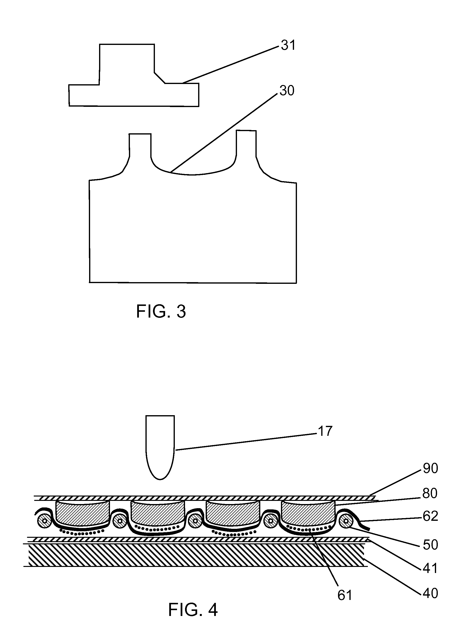
[0017]The method of the present invention differs from prior art first in that a mass of tough material is used not in an attempt to directly block the projectile, nor to deflect it, but to couple mass to it, and thus slow it down by transfer of kinetic energy. This process then may be repeated in sequential stages, whereby additional mass is coupled progressively to the projectile, causing more and more kinetic energy to be transferred from it.
[0018]Second, the method provides a method of restraining the motion of the coupled masses and projectiles, using a network of fibers. The fibers are constructed into a three dimensional arrangement which allows the fibers to elongate elastically or plastically under favorable mechanical conditions so that they exert a progressive restraining force.
[0019]The nature of the restraining force is also of novel design in the present invention, being of two combined sources. First, the fibers stretch and provide restraint due to their own tensile modulus. Second the fibers couple force to surrounding adjacent masses, causing these masses also to experience acceleration, and thereby coupling kinetic energy from the projectile to surrounding masses which are themselves not necessarily directly impacted by the projectile.
[0020]The manner in which energy is coupled to adjacent masses is by tensile loading of the fibers substantially in the direction of the fibers longitudinal axis and substantially in the direction of the projectile prior to impact. T

Problems solved by technology

The practical problem is that the kinetic energy of a high velocity ballistic projectile is high while the cross section is small, resulting in a very high specific energy upon initial impact.
Solid plate designs are inflexible, and often heavy.
Information on these materials and their application to ballistic armor is widely available in the literature, though specific details are not always accessible due to proprietary nature of some materials.
Practical use in protective body armor of solid plate material is commonly restricted to small critical protection areas, such as over the heart, used in combination with layered ballistic fiber vests.
Ballistic fiber vests are generally effective at providing protection against standard hand gun bullets, but are not effective protection against high velocity rifle bullets.
The method of the invention is also scalable, and the size and dimensions of the internal components can be adjusted to defeat heavy caliber projectile or artillery shells, however, such embodiments would not reasonably qualify as light weight for use in personal body armor such as a bullet proof vest.

Method used


Image

  • Method And Apparatus For Protecting Against Ballistic Projectiles
  • Method And Apparatus For Protecting Against Ballistic Projectiles
  • Method And Apparatus For Protecting Against Ballistic Projectiles

Examples


first embodiment

The First Embodiment

[0040]The first embodiment is a flexible bullet proof vest which provides the wearer protection from high velocity, high power rifle fire to within the inner surface deflection limit of 4.4 centimeters (1.73 inches) specified by the United States National Institute of Justice (NIJ Standard 0101.04). By high velocity, high power rifle, we specifically consider the standard NATO 7.62×51 mm cartridge, which is a common threat in current warfare. This first embodiment of the invention is designed to protect to NIJ Standard 0101.04 Type III which protects against 7.62 mm Full Metal Jacketed (FMJ) bullets (U.S. Military designation M80), with nominal masses of 9.6 grams (148 grains) at a reference velocity of 847 meters / second (2780 ft / s). The concept of flexibility is important in bullet proof vests. A solid or stiff vest is extremely uncomfortable to a human user, and can result in the vest not being worn. Non-flexible vests exist, but tend to be constructed to provi...

second embodiment

Description of Second Embodiment of the Invention

[0068]A second embodiment of the invention will now be disclosed. It is also a bullet proof vest, hereafter referred to as vest. This second embodiment differs from the first embodiment in the construction of the ballistic layers, which will be described in detail. However the principles of operation and function are the same as in the first embodiment. The general assembly and construction of the final garment is essentially similar to that of the first embodiment and will not be described here.

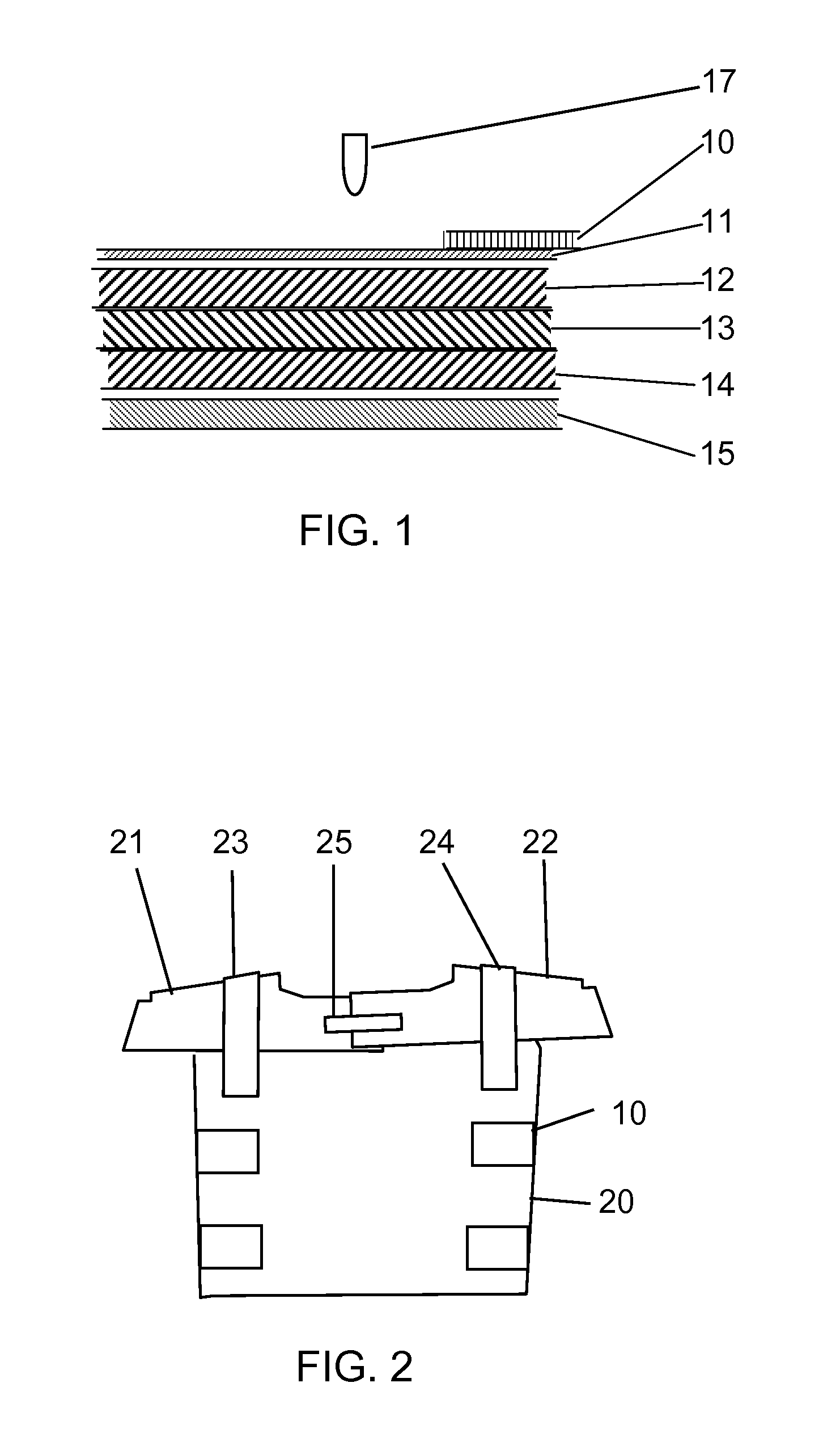
[0069]The vest is constructed of five layers. There are three ballistic function layers, as with the first embodiment. The outermost first layer (11) and innermost fifth layer (15) are the same as described in the first embodiment.

[0070]Details of the construction of the first ballistic layer of the second embodiment vest are shown in the cross section in FIG. 10. A plurality of square cross section discs (103) arranged in a regular square mat...

third embodiment

Description of Third Embodiment of the Invention

[0078]A third embodiment of the invention will now be disclosed. It is also a bullet proof vest, hereafter referred to as vest. This third embodiment differs in construction of the ballistic layers, one of which will be described in detail, however the principles of operation and function are the same as in the first and second embodiment. The general assembly and construction of the final garment is essentially similar to that of the first and second embodiment and will not be described.

[0079]The vest is constructed of five layers. There are three ballistic function layers, as with the first embodiment. The outermost first layer (11) and innermost fifth layer (15) are the same as described in the first embodiment.

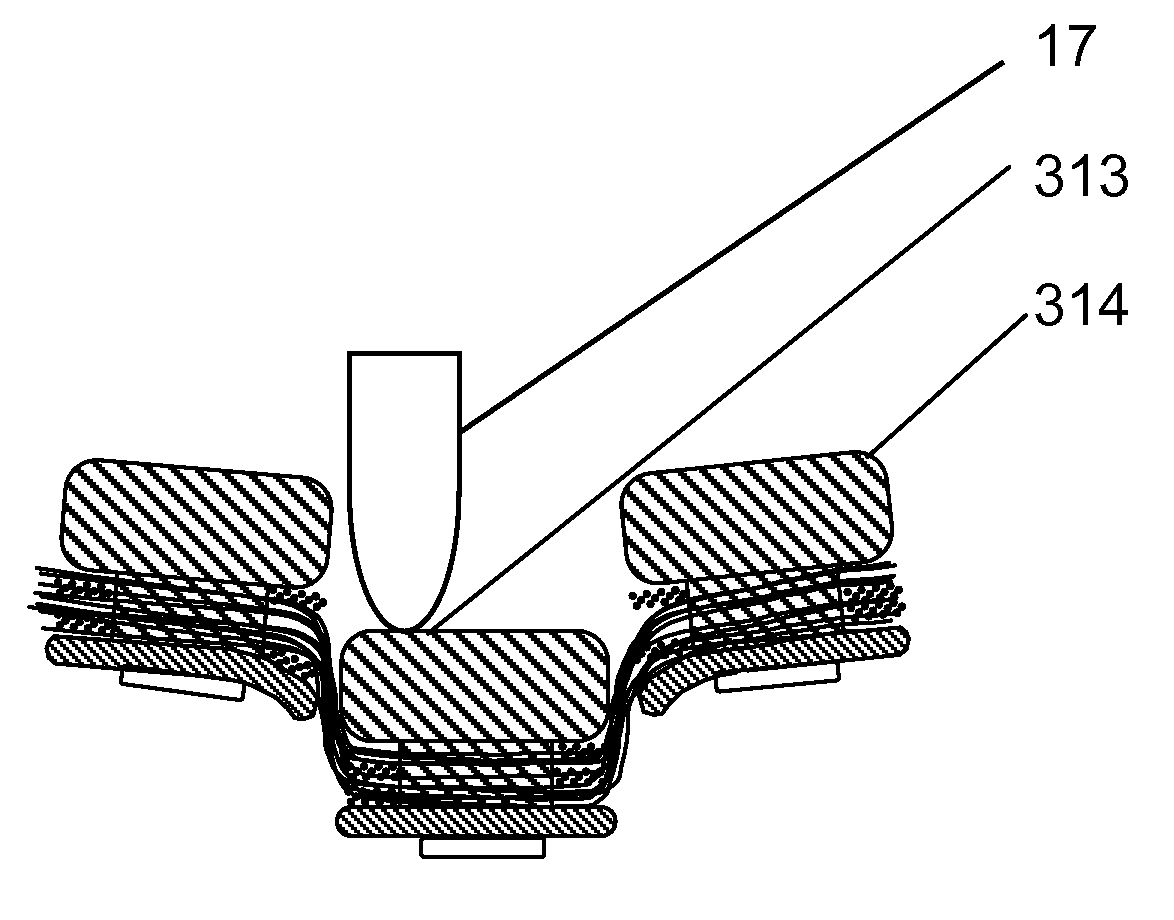
[0080]Details of the construction of the first ballistic layer of the third embodiment vest will now be described with reference to FIGS. 11, 12 and 13.

[0081]A plurality of square cross section multi-component discs (303) arr...


PUM

PropertyMeasurementUnit
Angleaaaaaaaaaa
Momentumaaaaaaaaaa
Forceaaaaaaaaaa

Abstract

A composite material comprising a multitude of masses and fibers supported on a flexible substrate arranged in a manner to absorb energy from a ballistic projectile and thereby protect persons or property from ballistic injury or damage. An array of small, tough disc-like masses are suspended in a three dimensional cradle of high-tensile elastomeric fibers such that energy from an incoming ballistic projectile is first imparted to one or more masses and the motion of the masses are restrained by tensile strain of elastomeric fibers substantially in the direction of travel of the incoming projectile. The projectile is eventually decelerated to harmless velocity through a combination of transfer of momentum to the masses and the elastic and plastic tensile deformation of the fibers. One or more layers of the composite material can be assembled to form body protective armor (“bullet-proof vest”) or property protective armor, the number and characteristics of the layers being adjusted according to the specific ballistic threat anticipated.

Description

BACKGROUND—FIELD OF INVENTION[0001]The present invention is in the field of protection of persons or property against kinetic missiles such as firearm bullets, specifically contemplated is application as ballistic body-armor (or “bullet-proof vests”) and also the protection of vehicles, including aircraft, and sensitive property such as communications equipment by providing flexible, light-weight protection against small arms and high-velocity rifle bullets.BACKGROUND—DESCRIPTION OF PRIOR ART[0002]The mechanical challenges of arresting a high velocity projectile have focused prior and current art on materials with extreme mechanical properties. The practical problem is that the kinetic energy of a high velocity ballistic projectile is high while the cross section is small, resulting in a very high specific energy upon initial impact. Under such conditions, inertial forces typically dominate over mechanical properties and the projectile will tend to punch through a layer of material ...

Claims


Application Information

Patent Timeline
IPC IPC(8): F41H1/02F41H5/02
CPCF41H5/0428F41H5/0457F41H5/0471
Inventor JBEILI, TERANCEPAYTON, CHRISTOPHER CHARLESATHERTON, ERIC JOHN
Owner ENERGY SCI
Why Eureka
Eureka Blog
Learn More