Laminated iron core, method and die machine for manufacturing the same

a technology die machine, which is applied in the manufacture of stator/rotor bodies, magnets, magnetic bodies, etc., can solve the problems of low cost performance, complicated production and prone to burrs in coil windings, so as to improve the electrical properties of laminated iron cores and enhance the electrical insulation between successive iron core pieces

Inactive Publication Date: 2008-12-18
KURODA PRECISION INDS
View PDF9 Cites 12 Cited by
  • Summary
  • Abstract
  • Description
  • Claims
  • Application Information

AI Technical Summary

Benefits of technology

[0013]According to the present invention, since the electrically insulating sheet piece includes the slot holes having a substantially similar configuration to said slot holes of the iron core piece but having a smaller size than said slot holes of the iron core pieces, when an electrically insulating sheet piece is provided on an outer surface of the lowermost iron core piece or two electrically sheet pieces are provided on outer surfaces of the lowermost and uppermost iron core pieces or more than two electrically insulating sheet pieces are provided between successive stacks of a given number of iron core pieces, the edges of the slot holes of the electrically insulating sheet pieces extend outwardly beyond edges of the slot holes of the iron core pieces. Therefore, upon winding a coil into the slot holes of the iron

Problems solved by technology

When a coil is wound into the slot holes, coil windings are liable to be injured by these burrs.
However, such methods require additional processes such as the barrel finishin

Method used


Image

  • Laminated iron core,  method and die machine for manufacturing the same
  • Laminated iron core,  method and die machine for manufacturing the same
  • Laminated iron core,  method and die machine for manufacturing the same

Examples


first embodiment

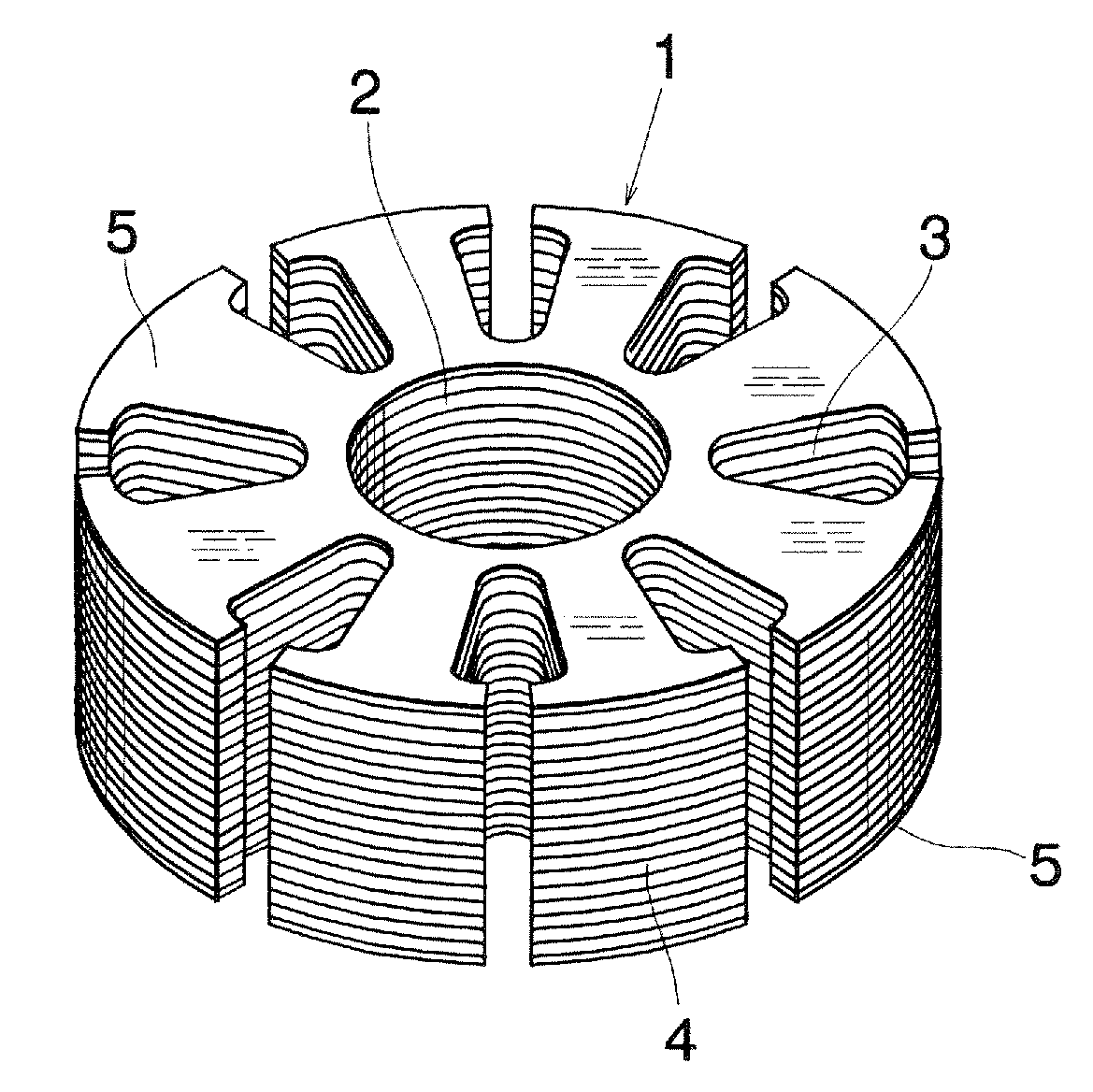
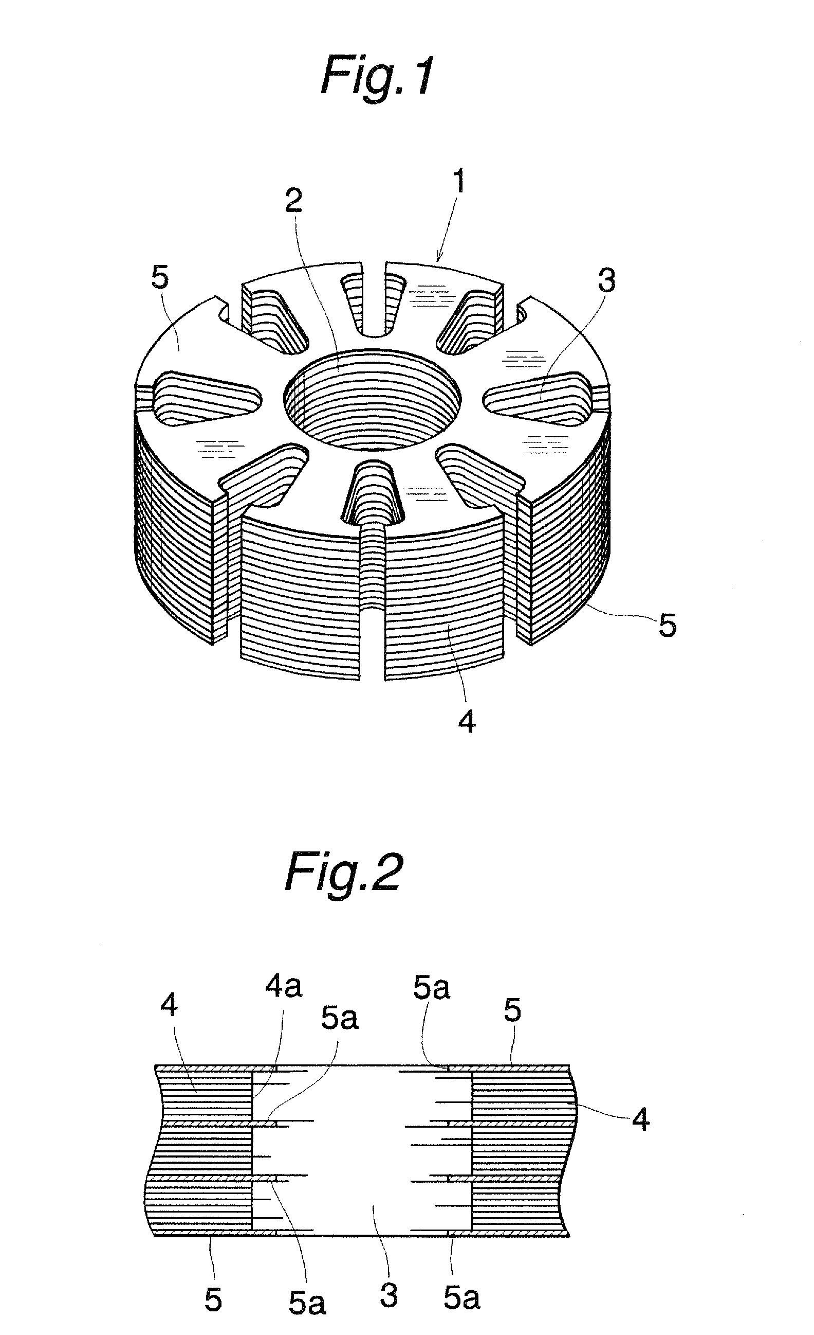
[0025]FIG. 1 is a perspective view showing the laminated iron core according to the present invention. A laminated iron core 1 includes a stack of a plurality of iron core pieces 4 each having a spindle hole 2 formed at a center and a plurality of slot holes 3 for receiving coil windings. The slot holes 3 are of an open slot type and the laminated iron core 1 has a substantially tubular configuration as a whole. The laminated iron core 1 further comprises electrically insulating sheet pieces 5 stacked together with the iron core pieces 4 to form the laminated iron core 1.

[0026]FIG. 2 is a cross sectional view of the laminated iron core of the present embodiment. As illustrated in FIG. 2, in the present embodiment, two electrically insulating sheet pieces 5 are provided on respective outer surfaces of the lowermost and uppermost iron core pieces 4 and two electrically insulating sheet pieces 5 are provided between successive stacks of eight iron core pieces 4. Each of the electricall...

third embodiment

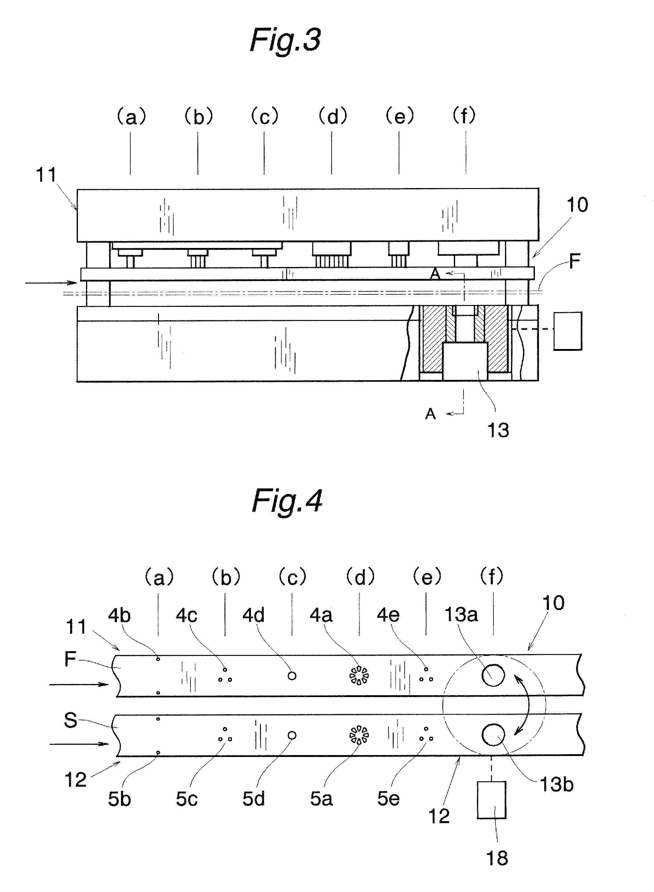
[0043]FIGS. 8 and 9 illustrate the die machine according to the invention. In this embodiment, a stacking die 31 for manufacturing a three pole motor core is constructed as a compound blanking die. That is to say, in the first working row 11, an iron core piece 4 including a spindle hole 2, slot holes 4a and clamping projections is formed or punched out by means of a single punch, and in the second working row 12, an electrically insulating sheet piece 5 including a spindle hole 2, slot holes 5a and clamping projections is punched by means of a single punch.

[0044]The stacking die 31 is arranged rotatably to move between the first and second working rows 11 and 12 like as the first embodiment. That is to say, when the stacking die 31 is indexed to the first working row 11, a given number of iron core pieces are punched out into the stacking die 31, and then after moving the stacking die 31 into the second working row 12, an electrically insulating sheet piece is punched out onto a st...


PUM


Abstract

A laminated iron core includes a plurality of stacked iron core pieces punched out from a thin steel sheet material, each iron core piece including a plurality of slot holes for receiving coil windings. At least one electrically insulating sheet piece is stacked on an outer surface of a lowermost iron core piece. The electrically insulating sheet pieces include a spindle hole and a plurality of slot holes which have a substantially similar configuration to, but are smaller than, the slot holes of the iron core pieces whereby edges of slot holes of electrically insulating sheet pieces extend outwardly beyond edges of slot holes of iron core pieces. Burrs formed at edges of slot holes of iron core pieces are covered with edges of slot holes of electrically insulating sheet pieces so that a coil can be wound safely without directly contacting the burrs.

Description

CROSS REFERENCE TO RELATED APPLICATION[0001]The present application is a Divisional Application of U.S. application Ser. No. 11 / 284,618 filed Nov. 22, 2005, which is incorporated herein by reference.TECHNICAL FIELD[0002]The present invention relates to a laminated iron core for a motor comprising a stack of a plurality of iron core pieces each having slot holes for receiving coil windings. The present invention also relates to a method of manufacturing such a laminated iron core, and also relates to a mold for use in such a method.TECHNICAL BACKGROUND[0003]Iron core pieces for use in a motor core are generally formed by a successively transferring die or mold, in which core pieces are punched out by means of a punch into a die. Therefore, burrs are produced along punched edges, and particularly burrs are generated along edges of slot holes. When a coil is wound into the slot holes, coil windings are liable to be injured by these burrs.[0004]In order to avoid such disadvantage, in Ja...

Claims


Application Information

Patent Timeline
IPC IPC(8): H02K15/02
CPCB21D28/22B32B15/18H01F41/0233H02K3/34H02K15/024Y10T29/5317Y10T29/49012Y10T29/5142Y10T29/53143Y10T29/5192Y10T29/49009Y10T29/49078
Inventor NISHIZAWA, TAKESHIHORII, HIDEO
Owner KURODA PRECISION INDS
Why Eureka
Try Eureka