Method and Apparatus for Precisely Measuring Wire Tension and Other Conditions, and High-Sensitivity Vibration Sensor Constructed in Accordance Therewith

a technology of vibration sensor and wire tension, which is applied in the direction of reradiation, fluid solid analysis using sonic/ultrasonic/infrasonic waves, etc., can solve the problem of low sensitivity of longitudinal or transverse wave measurement method, which is relatively high compared to the prior art, and achieves high sensitivity and precision. , the effect of high sensitivity

Inactive Publication Date: 2008-12-18
NEXENSE
View PDF6 Cites 26 Cited by
  • Summary
  • Abstract
  • Description
  • Claims
  • Application Information

AI Technical Summary

Benefits of technology

[0005]An object of the present invention is to provide a novel method and a novel apparatus for monitoring predetermined conditions which method and apparatus have a capability of extremely high sensitivity and precision. Another object of the invention is to provide a method an apparatus for precisely measuring tension in a tensioned member, especially in a tensioned wire. A still further object of the present invention is to provide a highly-sensitive vibration sensor particularly useful for measuring earth vibrations.

Problems solved by technology

Such elongation is very small relative to the tensile force, and therefore the sensitivity of the measuring method with longitudinal or transverse waves, although relatively high compared to the prior art, is relatively low compared to what is theoretically possible.

Method used


Image

  • Method and Apparatus for Precisely Measuring Wire Tension and Other Conditions, and High-Sensitivity Vibration Sensor Constructed in Accordance Therewith
  • Method and Apparatus for Precisely Measuring Wire Tension and Other Conditions, and High-Sensitivity Vibration Sensor Constructed in Accordance Therewith
  • Method and Apparatus for Precisely Measuring Wire Tension and Other Conditions, and High-Sensitivity Vibration Sensor Constructed in Accordance Therewith

Examples


Embodiment Construction

Overview

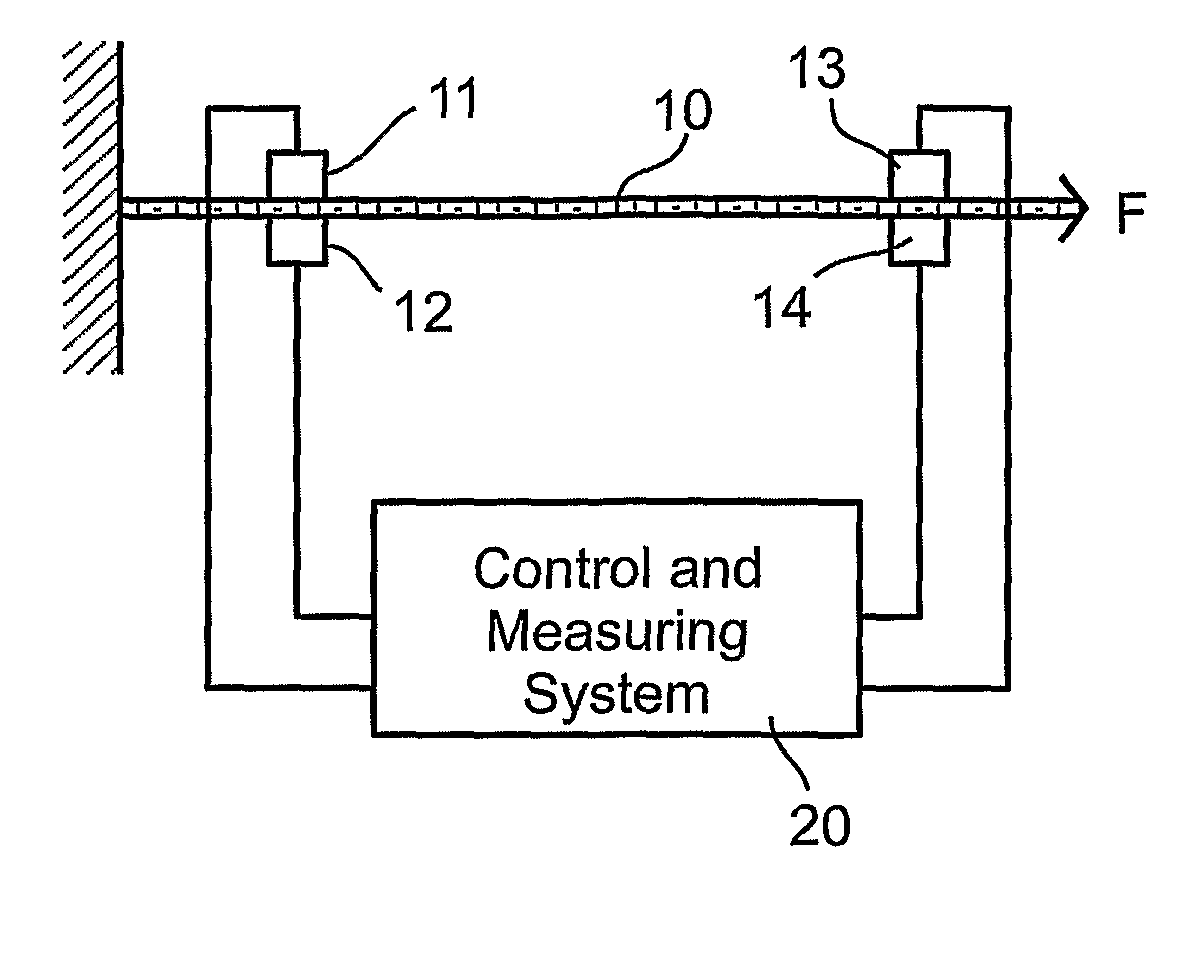
[0028]FIG. 1 illustrates the invention embodied in a tensioned wire 10, which is tensioned by a tensile force, indicated by arrow F, to be measured.

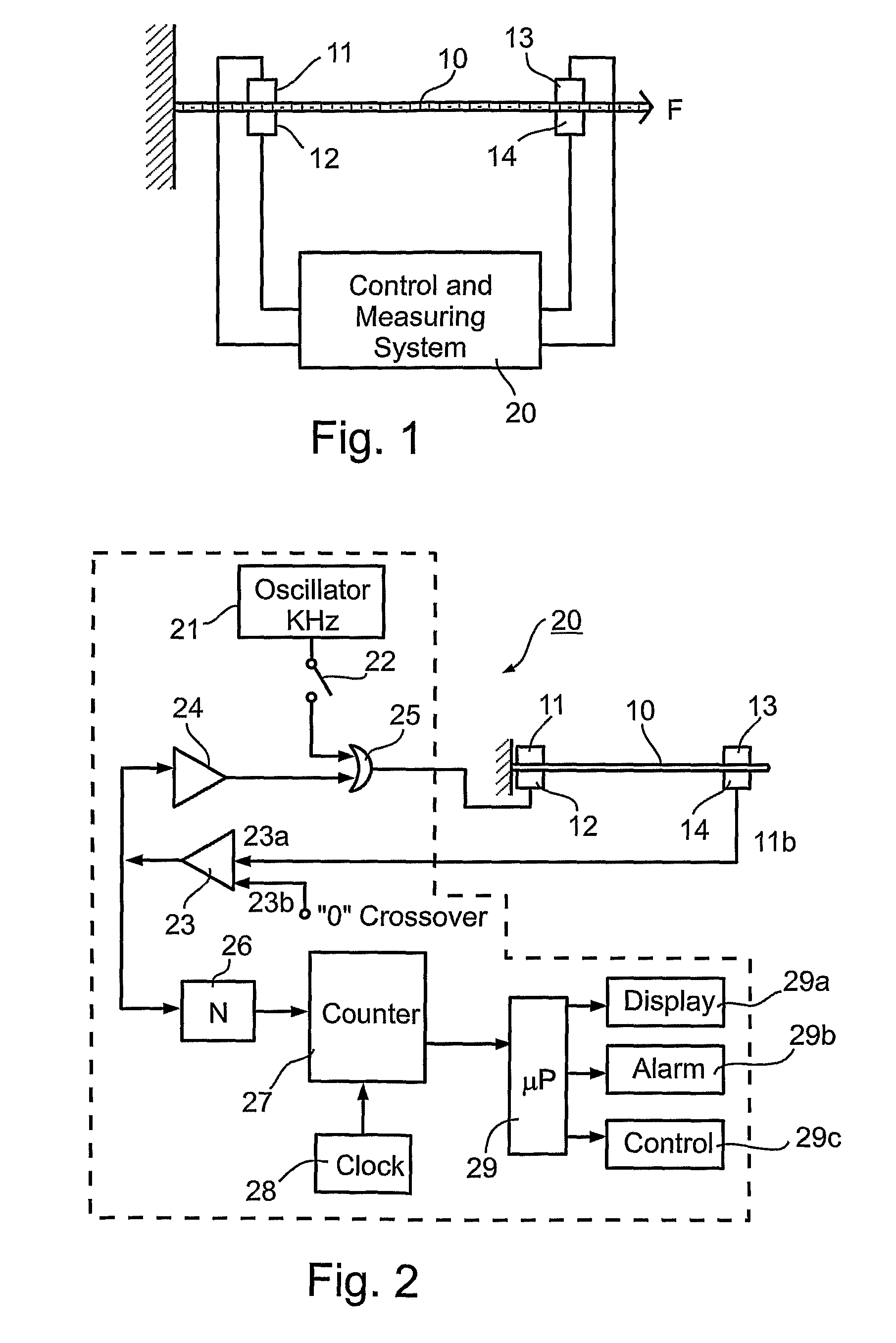
[0029]The illustrated apparatus includes a first pair of piezoelectric devices 11, 12 at a first location on the tensioned wire 10 for generating acoustical waves which propagate longitudinally along the length of the tensioned wire; and a second pair of piezoelectric devices 13, 14 at a second location, spaced from the first location of piezoelectric devices 11, 12 by at least one wavelength, for sensing or receiving the generated acoustical waves. The two pairs of piezoelectric devices 11, 12 and 13, 14 are controlled by a control and measuring system, generally designated 20, constructed as described in the above-cited US patent and published application and illustrated in FIG. 2 of the present application. As will be described more particularly below, system 20 controls piezoelectric devices 11, 12 so as to vary the frequency...


PUM

PropertyMeasurementUnit
resonant frequencyaaaaaaaaaa
transit timeaaaaaaaaaa
frequencyaaaaaaaaaa

Abstract

A method and apparatus for monitoring a predetermined condition of a medium by; transmitting acoustical waves through the medium, continuously measuring changes in the transit time of the acoustical waves resulting from changes in the monitored condition; and utilizing the changes in transit time to provide a continuous measurement of the changes in the monitored condition. The acoustical waves are bending waves wherein cross-sections of the medium have a rotational movement orthogonally to the axis of propagation of the waves through the acoustical channel. Several examples of such method and apparatus are described, including a highly sensitive pressure sensor for sensing changes in pressure applied to a displaceable membrane, and a highly-sensitive vibration sensor for sensing earth or other vibrations.

Description

FIELD AND BACKGROUND OF THE INVENTION[0001]The present invention relates to a method and apparatus for monitoring predetermined conditions which influence the transit velocity of an acoustical wave through a medium. The invention is particularly useful for monitoring changes in tension of a tensioned member, especially of a wire, and is therefore described below with respect to such application. Two implementations of the invention are described below for purposes of example, including a highly-sensitive pressure sensor for sensing pressure changes as detected by a membrane, and a highly-sensitive vibration sensor for sensing vibrations in the earth or other bodies.[0002]The present invention is particularly useful in the high-precision method and apparatus described in commonly-assigned U.S. Pat. No. 6,621,278 and published U.S. patent application Ser. No. 10 / 844,398, the contents of which patent and published application are expressly incorporated herein by reference. The inventio...

Claims


Application Information

Patent Timeline
Patent Type & Authority Applications(United States)
IPC IPC(8): G01N29/07
CPCG01H5/00G01L5/042G01L9/0013G01N29/07G01N2291/02827G01N2291/048G01N2291/102
Inventor RAVITCH, VLADIMIRBERNSTEIN, MICHAELARIAV, ARIE
Owner NEXENSE
Why Eureka
Try Eureka