Liquid crystal display and liquid crystal drive circuit

Inactive Publication Date: 2008-12-18
SONY CORP
View PDF14 Cites 17 Cited by
  • Summary
  • Abstract
  • Description
  • Claims
  • Application Information

AI Technical Summary

Benefits of technology

[0011]In view of the foregoing, it is desirable to provide a liquid crystal display and a liquid crystal drive circuit ca

Problems solved by technology

This means that the improvement of the response speed of the liquid crystal is insufficient.
However, as a result, the electric power consumption is increased or the heat release value is increased so that issues including a decrease of reliabilit

Method used


Image

  • Liquid crystal display and liquid crystal drive circuit
  • Liquid crystal display and liquid crystal drive circuit
  • Liquid crystal display and liquid crystal drive circuit

Examples


Example

[0032]Preferred embodiments of the present invention will be described in detail with reference to the accompanying drawings.

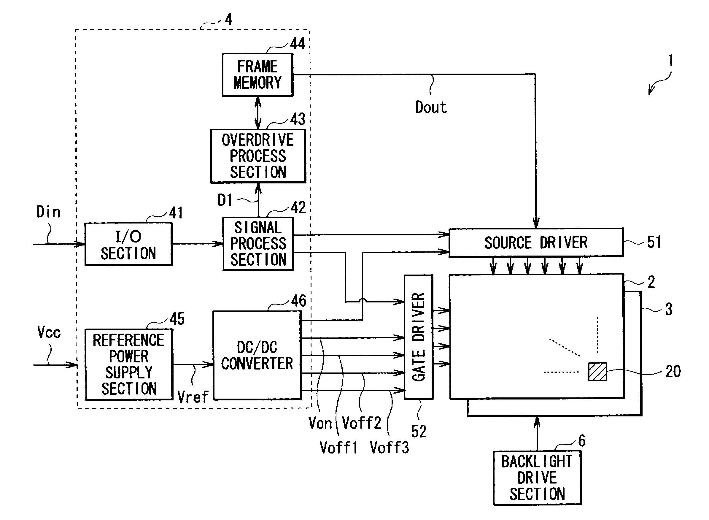
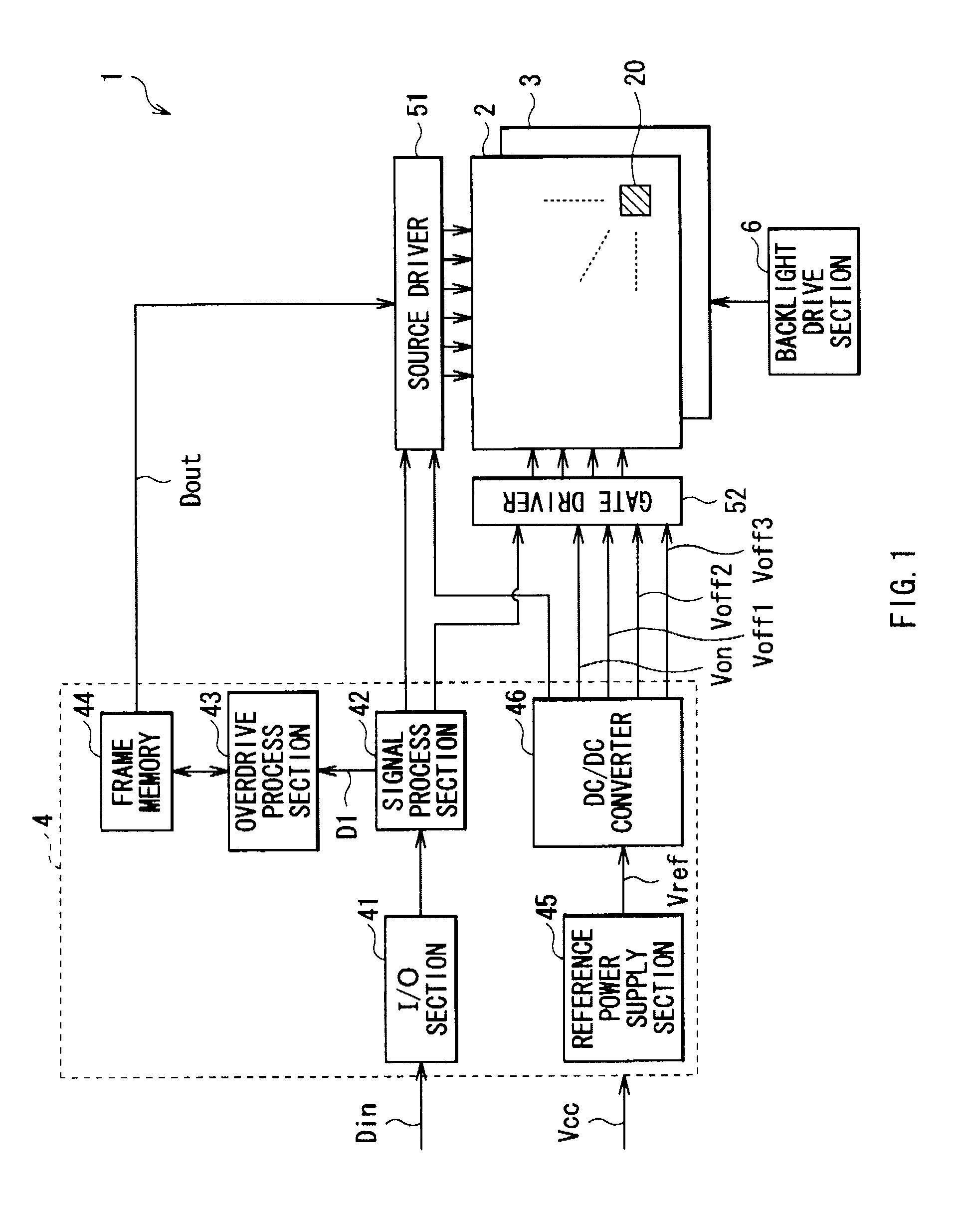
[0033]FIG. 1 shows an overall configuration of a liquid crystal display (liquid crystal display 1) according to an embodiment of the present invention. The liquid crystal display 1 includes a liquid crystal display panel 2, a backlight section 3, a timing controller 4, a source driver 51 and a gate driver 52, and a backlight drive section 6.

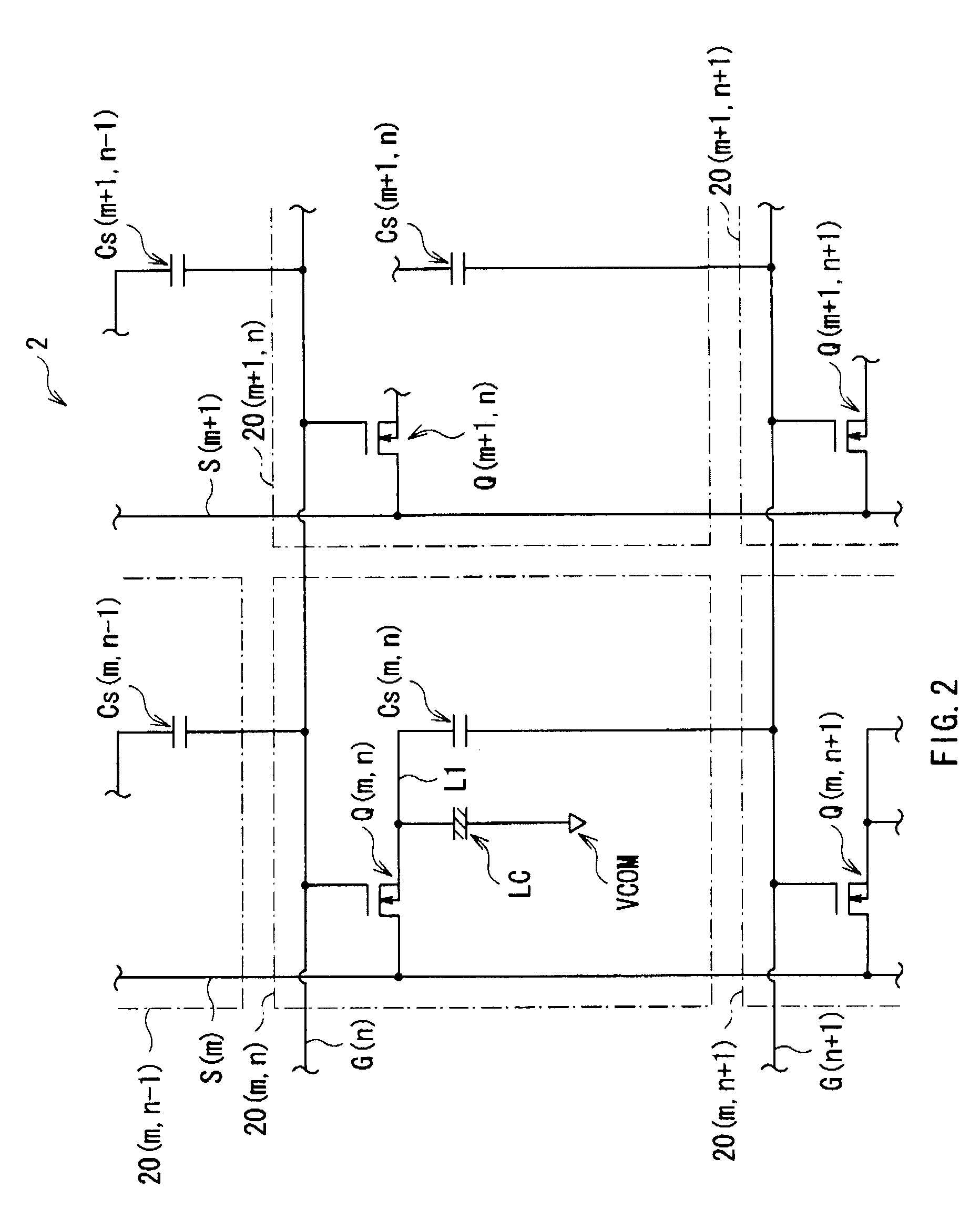
[0034]The liquid crystal display panel 2 performs an image display on the basis of an input image signal Din by a drive signal supplied from the source driver 51 and the gate driver 52 which will be described later. The liquid crystal display panel 2 includes a plurality of pixels 20 disposed side by side in a matrix shape. In each of the pixels 20, a pixel circuit unit (refer to FIG. 2) which will be described later is formed. The detailed configuration of the pixel circuit unit will be described later.

[0035]The backlight ...


PUM


Abstract

A liquid crystal display includes pixels, gate lines, source lines and a drive means. Each of the pixels includes a TFT element, a liquid crystal element and an auxiliary capacitive device. One end of the liquid crystal device is connected to one end of the TFT device, and the auxiliary capacitive device is provided to be connected between the one end of the TFT device and an adjacent gate line. In a normal drive mode, the drive means drives each pixel on the basis of an image data acquired through correction which allows image luminance level of the current unit frame to be lowered by a predetermined amount. In an overdrive mode, the drive means drives each pixel on the basis of an image data which brings a larger amount of change of a voltage across the liquid crystal device between the previous unit frame and the current unit frame.

Description

CROSS REFERENCES TO RELATED APPLICATIONS[0001]The present invention contains subject matter related to Japanese Patent Application JP 2007-155274 filed in the Japanese Patent Office on Jun. 12, 2007, the entire contents of which being incorporated herein by reference.BACKGROUND OF THE INVENTION[0002]1. Field of the Invention[0003]The present invention relates to a liquid crystal display including an auxiliary capacitive element, and a liquid crystal drive circuit applied to such a liquid crystal display.[0004]2. Description of the Related Art[0005]In recent years, there have been widely utilized liquid crystal displays which display video images by driving display elements (liquid crystal elements) using liquid crystal. In such a liquid crystal display, light from a light source is transmitted and modulated by changing an alignment of liquid crystal molecules in a liquid crystal layer sealed between substrates such as glass substrates, and thereby displays are performed.[0006]Also, ...

Claims


Application Information

Patent Timeline
IPC IPC(8): G09G3/36
CPCG09G3/3648G09G3/3677G09G2300/0876G09G2320/0252G09G2320/103
Inventor FURUKOSHI, YASUTAKE
Owner SONY CORP
Why Eureka
Try Eureka