
Driving circuit of liquid crystal display device and method for driving the same

Active Publication Date: 2008-12-18
LG DISPLAY CO LTD
View PDF5 Cites 34 Cited by
  • Summary
  • Abstract
  • Description
  • Claims
  • Application Information

AI Technical Summary

Benefits of technology

[0009]An object of the present invention is to provide a driving circuit of a liquid crystal display device and a method for driving the same, which are capable of reducing manufacturing cost of the liquid crystal display device and reducing a luminance deviation so as to improve image quality.

Problems solved by technology

However, in a conventional liquid crystal display device, manufacturing cost is increased due to respective photosensors mounted in the division areas and a luminance deviation between the division areas is generated so as to deteriorate image quality.
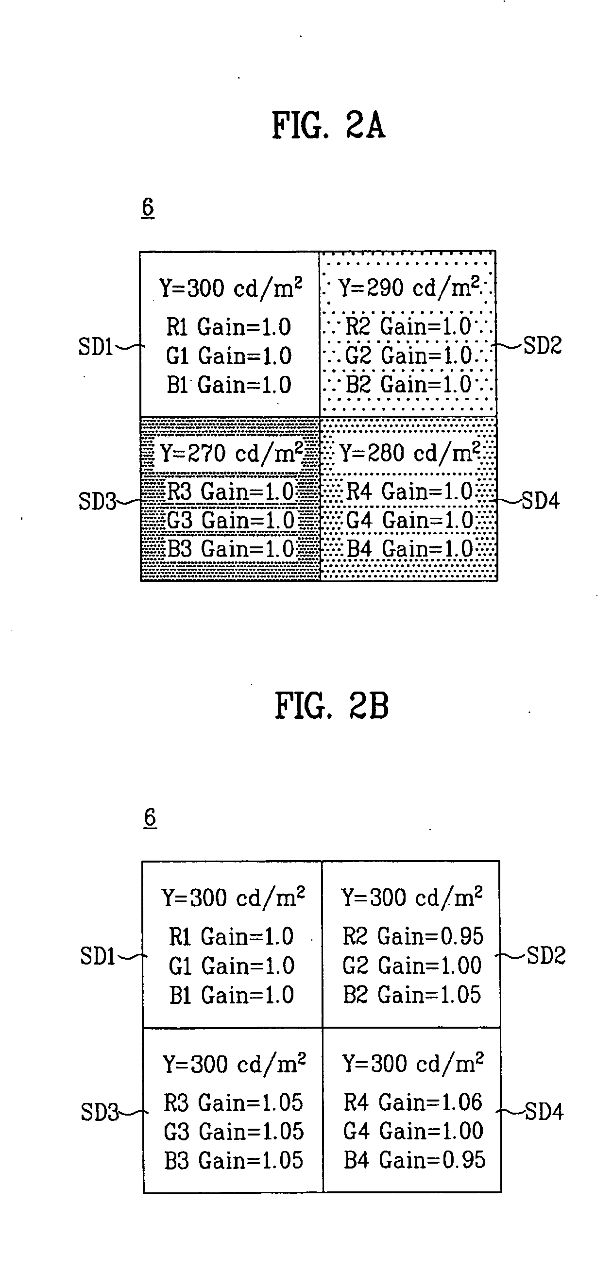
The luminance of a specific area deteriorates by a temperature deviation between the division areas, a driving voltage deviation and an emission time deviation between the LEDs, thereby generating display unevenness.

Method used


Image

  • Driving circuit of liquid crystal display device and method for driving the same
  • Driving circuit of liquid crystal display device and method for driving the same
  • Driving circuit of liquid crystal display device and method for driving the same

Examples


Embodiment Construction

[0021]Reference will now be made in detail to the preferred embodiments of the present invention, examples of which are illustrated in the accompanying drawings. Wherever possible, the same reference numbers will be used throughout the drawings to refer to the same or like parts.

[0022]Hereinafter, a driving circuit of a liquid crystal display device and a method for driving the same according to embodiments of the present invention will be described with reference to the accompanying drawings.

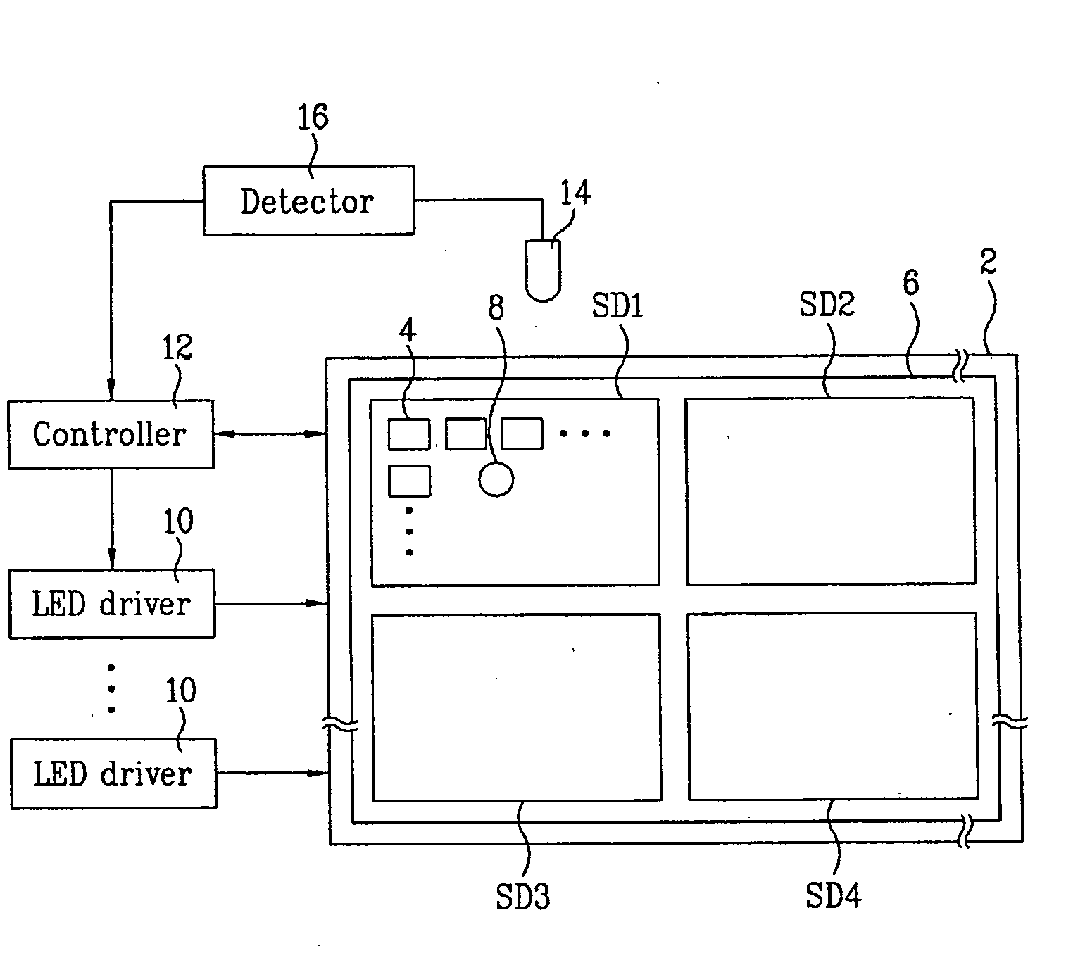
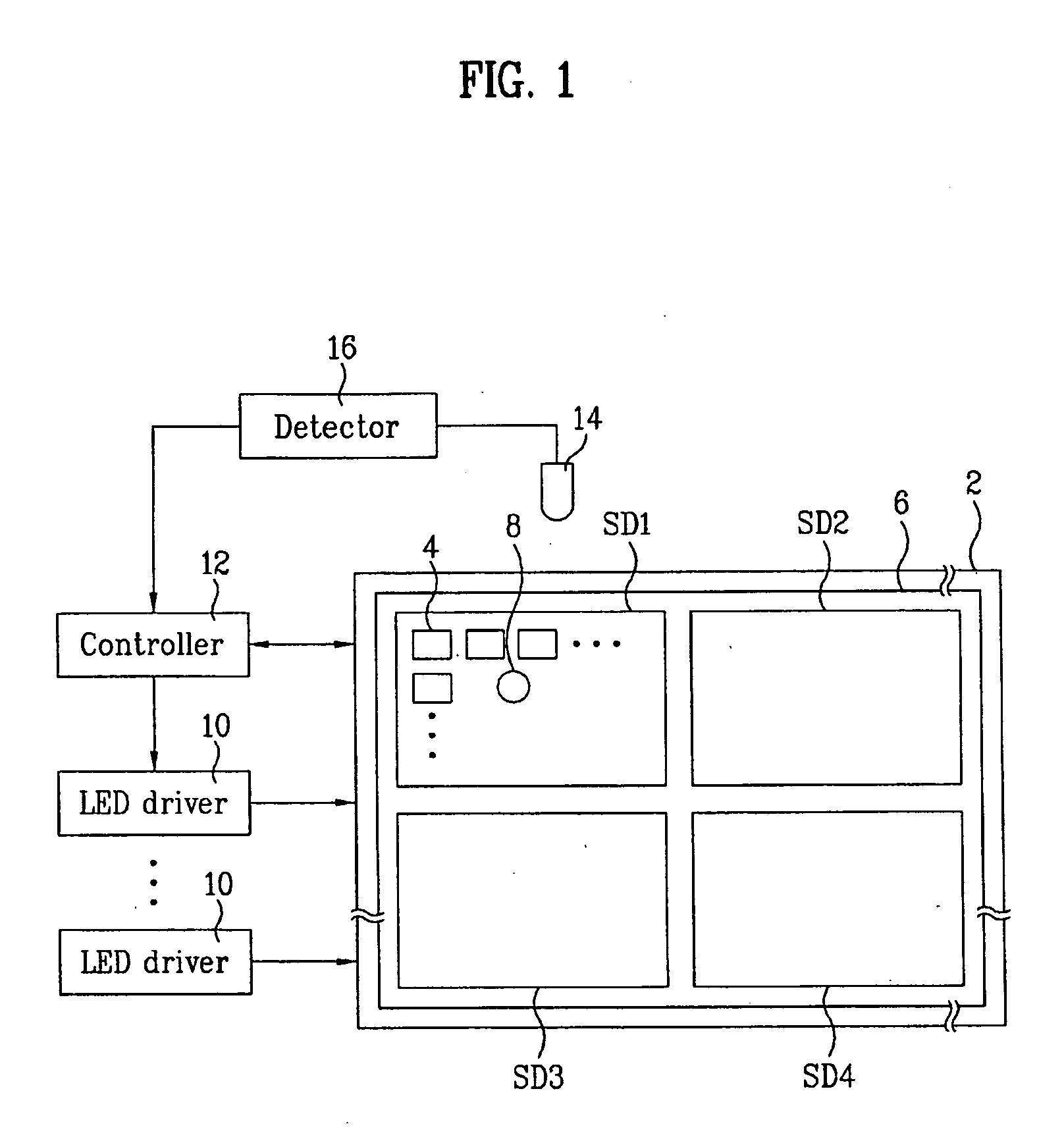
[0023]FIG. 1 is a block diagram showing the configuration of a liquid crystal display device according to an embodiment of the present invention.

[0024]The liquid crystal display device shown in FIG. 1 includes a liquid crystal panel 2 in which a plurality of pixel areas are included, a LED backlight 6 which includes a plurality of LED modules 4 arranged in a plurality of division areas SD1 to SD4 and irradiates light onto the liquid crystal panel 2, an internal photosensor 8 for detecting a lum...


PUM


Abstract

A driving circuit of a liquid crystal display device and a method for driving the same, which are capable of reducing manufacturing cost of the liquid crystal display device and reducing a luminance deviation so as to improve image quality, are disclosed. The driving circuit of the liquid crystal display device includes an LED backlight which includes a plurality of LED modules arranged in a plurality of division areas and generates light, an internal photosensor which is mounted in any one of the plurality of division areas, for detecting a luminance value, a controller which generates and outputs a plurality of control signals for changing respective luminance values of the plurality of division areas according to the luminance value detected by the internal photosensor, and a plurality of LED drivers which drive the plurality of LED modules according to the plurality of control signals.

Description

[0001]This application claims the benefit of Korean Patent Application No. 10-2007-058761, filed on Jun. 15, 2007 which is hereby incorporated by reference as if fully set forth herein.BACKGROUND OF THE INVENTION[0002]1. Field of the Invention[0003]The present invention relates to a liquid crystal display device, and more particularly, to a driving circuit of a liquid crystal display device and a method for driving the same, which are capable of reducing manufacturing cost of the liquid crystal display device and reducing a luminance deviation so as to improve image quality.[0004]2. Discussion of the Related Art[0005]A general liquid crystal display device displays an image by adjusting light transmission of liquid crystal having dielectric anisotropy using an electric field. The liquid crystal display device includes a liquid crystal panel in which pixel areas are arranged in a matrix, a driving circuit for driving the liquid crystal panel, and a backlight unit for irradiating ligh...

Claims


Application Information

Patent Timeline
IPC IPC(8): G02F1/13357G09G3/36
CPCG09G3/3426G09G2320/0233G09G2320/064G09G2320/0666G09G2360/145G02F1/133
Inventor YANG, JUN HYEOK
Owner LG DISPLAY CO LTD
Learn More