Nozzle plate, droplet discharge head, method for manufacturing the same and droplet discharge device

a technology of droplet and nozzle, which is applied in the direction of printing, etc., can solve the problems of increasing the density of the nozzle, the difficulty of maintaining a straight flying property of the droplet, and the inability to maintain a meniscus stably, so as to improve the discharge characteristics, prevent the turbulence of the ink flow, and increase the nozzle density

Active Publication Date: 2008-12-18
SEIKO EPSON CORP
View PDF1 Cites 38 Cited by
  • Summary
  • Abstract
  • Description
  • Claims
  • Application Information

AI Technical Summary

Benefits of technology

[0017]An advantage of the invention is to provide a nozzle plate, a droplet discharge head, a method for manufacturing the same, and a droplet discharge device that can improve discharge characteristics and increase nozzle density.
[0018]A nozzle plate according to a first aspect of the invention includes a silicon substrate, and a nozzle hole formed in the silicon substrate for discharging a liquid droplet. The nozzle hole is provided with a first nozzle portion formed perpendicularly to a surface of the silicon substrate, a second nozzle portion formed on a same axis as an axis of the first nozzle portion and having a cross-sectional area that is larger than a cross-sectional area of the first nozzle portion, and an inclined portion having a cross-sectional area gradually increasing from the first nozzle portion to the second nozzle portion.
[0019]In the nozzle shape and nozzle structure as the above, the first nozzle portion and the second nozzle portion are joined through the inclined portion without a stepped portion, preventing turbulence of the ink flow and enabling the ink flow to be aligned to discharge in a central axis direction of the nozzle hole. Therefore, discharge characteristics are improved.
[0020]In this case, the cross-sectional area of the second nozzle portion and the cross-sectional area of the inclined portion are preferably shaped in one of a square shape and a rectangular shape.
[0021]The cross-sectional area of the second nozzle portion and the cross-sectional area of the inclined portion are in a shape that is not restricted by a crystal orientation of silicon, thereby enabling high densification of nozzles.
[0022]A method for manufacturing a nozzle plate according to a second aspect of the invention includes: forming a nozzle hole in a silicon substrate by anisotropic dry etching, the nozzle hole including a first nozzle perpendicular to a surface of the silicon substrate, and a second nozzle formed on a same axis as an axis of the first nozzle portion and having a cross-sectional area that is larger than a cross-sectional area of the first nozzle portion and shaped in a polygonal shape; forming a protection film on a whole of an inner wall of the nozzle hole; selectively removing the protective film formed on a stepped portion between the first nozzle portion and the second nozzle portion; and forming an inclined portion by anisotropic wet etching so that the inclined portion has a cross-sectional area gradually reducing from the second nozzle portion to the first nozzle portion.

Problems solved by technology

Therefore, increasing the nozzle density is limited.
Further, an end of the nozzle becomes in a square shape due to the surface orientation of the silicon, making it hard to maintain a droplet straight flying property.
Furthermore, since a discharge outlet of the nozzle does not have a perpendicular portion, it is hard to stably maintain a meniscus.
In JP-A-2006-45656 (FIGS. 4 and 16), undercuts in sidewalls of the nozzle proceed due to isotopic dry etching, causing difficulty in controlling a diameter of the nozzle.
Further, since a discharge outlet of the nozzle does not have a perpendicular portion, it is hard to stably maintain a meniscus.
Therefore, increasing the nozzle density is limited.
Further, since alignment of both sides of the tapered portion and the perpendicular portion of the nozzle is required, accuracy is inferior to a case where alignment is performed from one side to be processed.
Therefore, increasing the nozzle density is limited.
Further, a border of the tapered portion and a perpendicular portion of the nozzle becomes indefinite, making it difficult to adjust a flow path resistance of the nozzle, that is, to adjust a length of the nozzle.
In JP-A-11-28820 (FIGS. 3 and 4), there is a stepped portion in a cylindrical shape between the first nozzle portion and the second nozzle portion, and thus stagnation of the ink flow occurs at the stepped portion, causing issues such as disturbance of flow and increase of a flow path resistance.

Method used


Image

  • Nozzle plate, droplet discharge head, method for manufacturing the same and droplet discharge device
  • Nozzle plate, droplet discharge head, method for manufacturing the same and droplet discharge device
  • Nozzle plate, droplet discharge head, method for manufacturing the same and droplet discharge device

Examples


Embodiment Construction

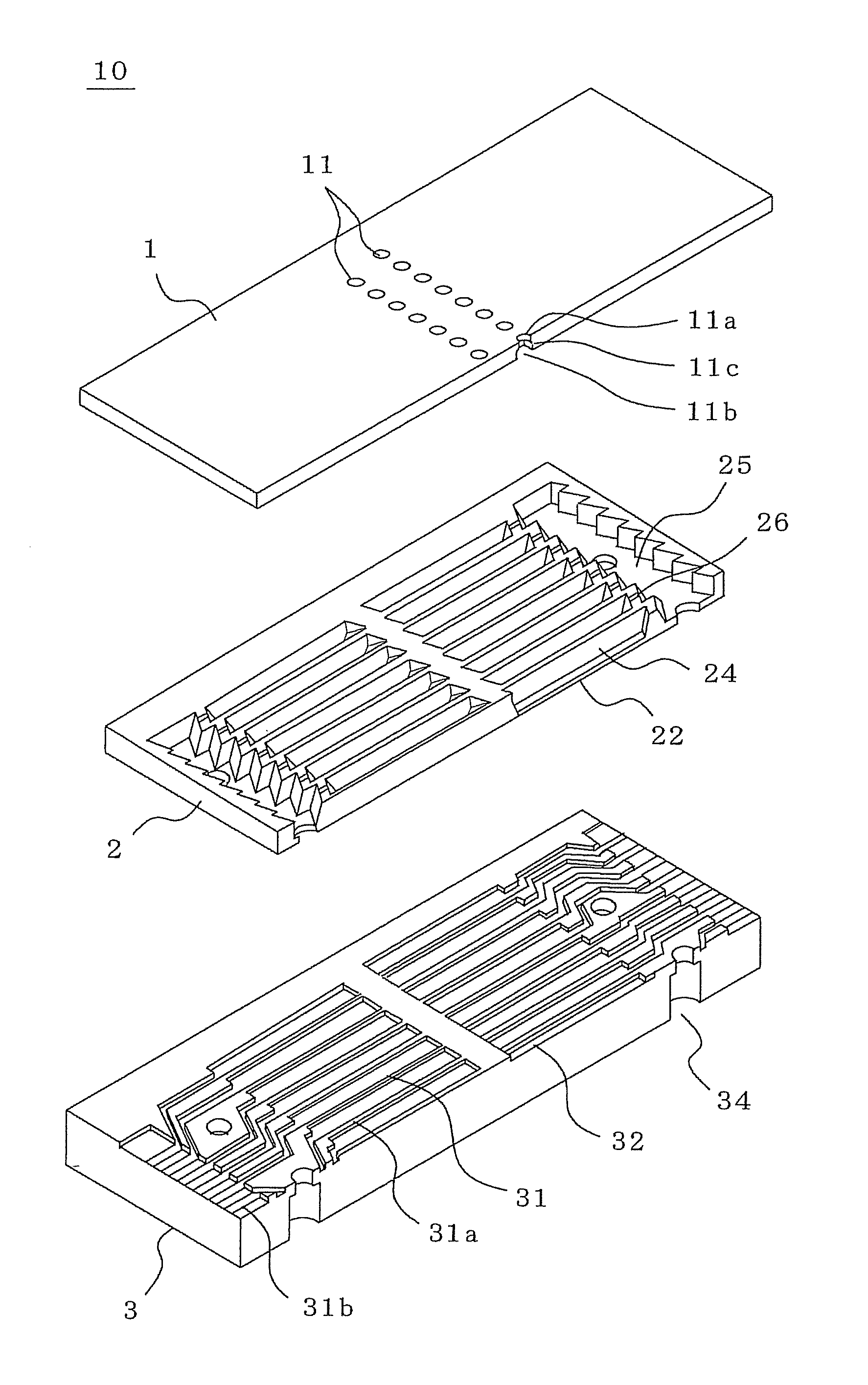
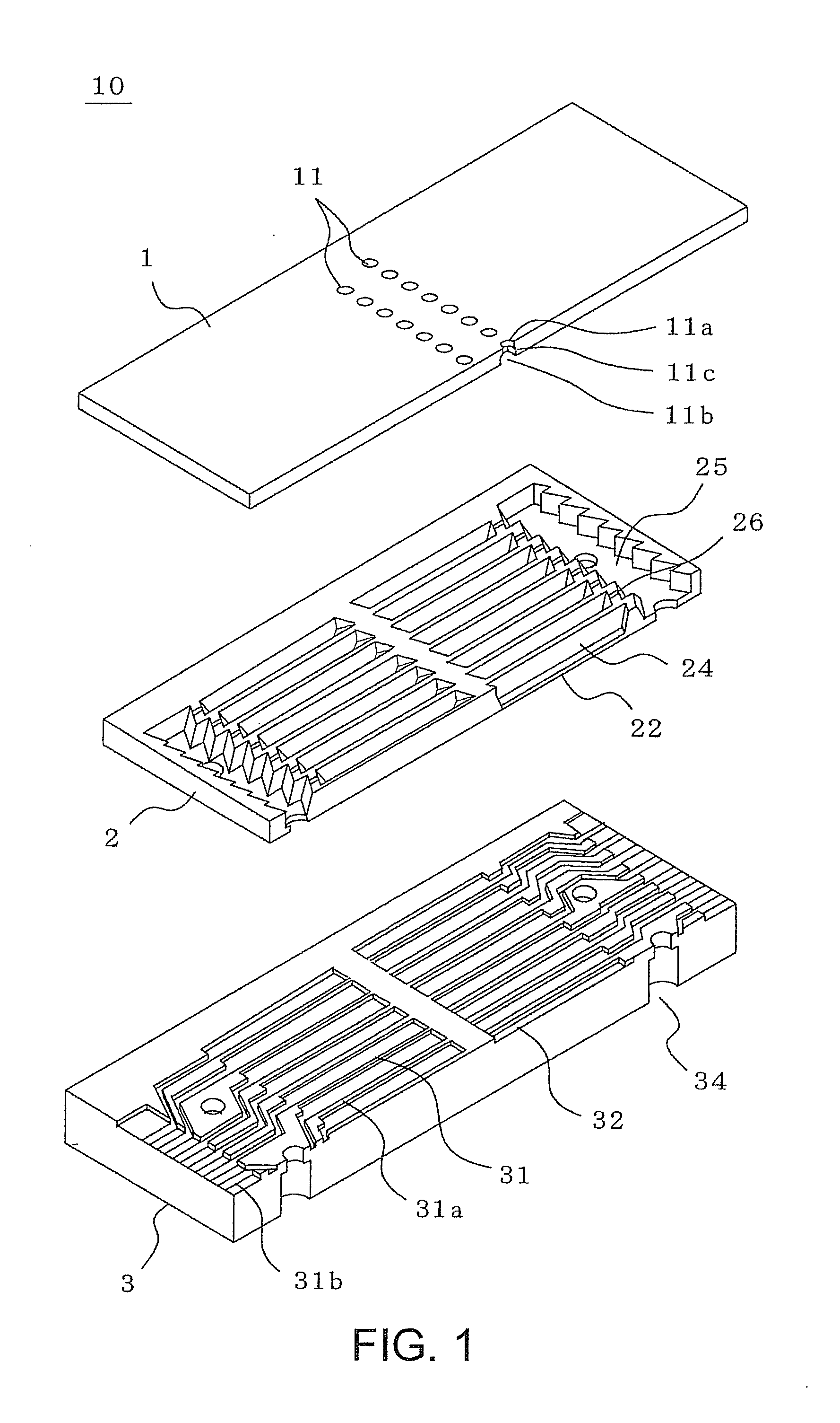
[0042]An embodiment of a droplet discharge head provided with a nozzle plate according to the invention will be described with reference to the accompanying drawings. Here, as an example of the droplet discharge head, an inkjet head in an electrostatic drive system is described referring to FIGS. 1 through 4B. The invention is not limited to the structure and shape shown in the figures below except for the nozzle shape. Further, the invention can be applicable not only to a face discharge type, but also an edge discharge type. Furthermore, since the drive system is not an exception, the invention is also applicable to a droplet discharge head and a droplet discharge device for discharging a droplet driven by any other drive systems.

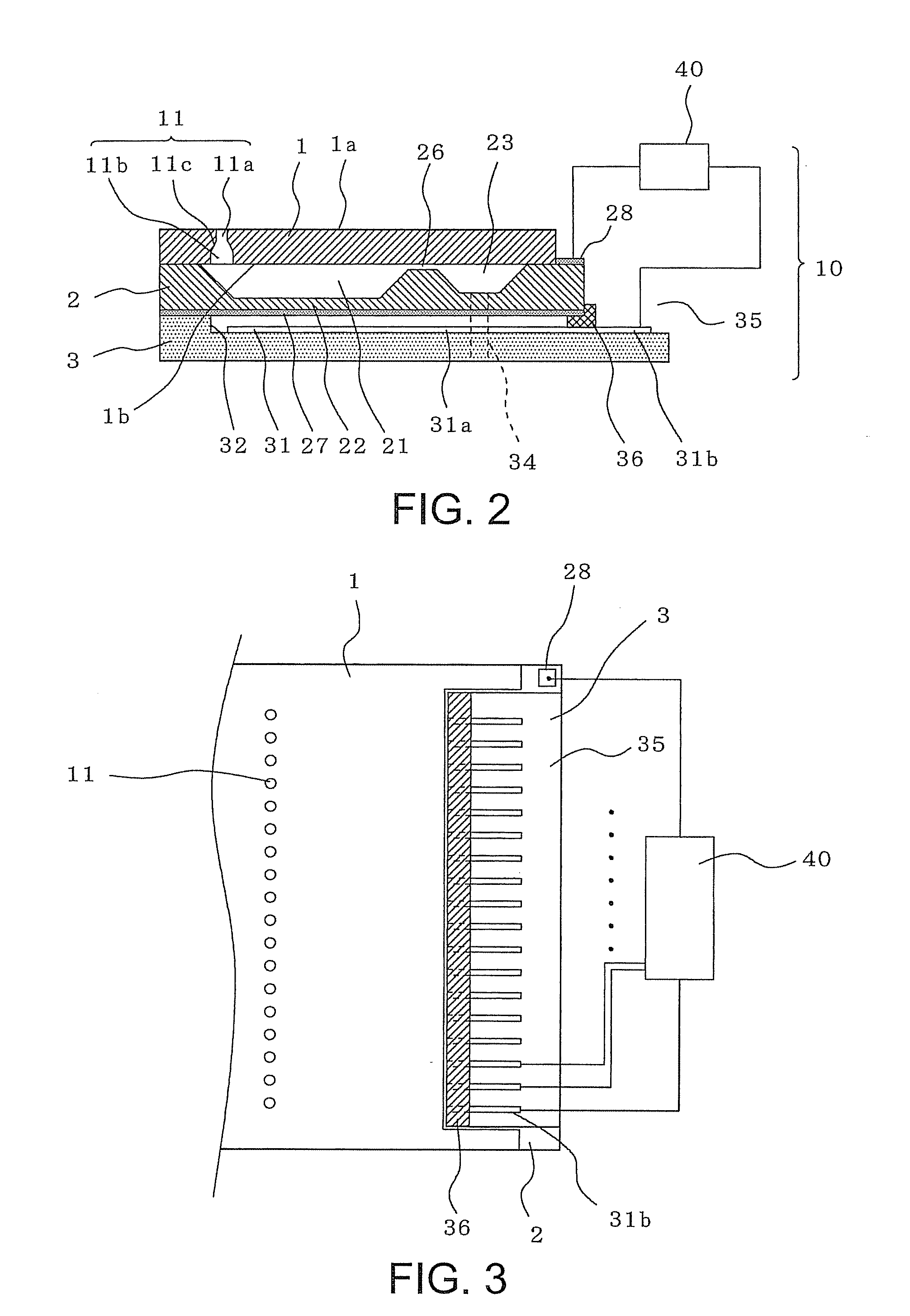
[0043]FIG. 1 is an exploded perspective view shown by disassembling a schematic structure of an inkjet head according to an embodiment, in which a part thereof is shown in section. FIG. 2 is a sectional view of the inkjet head showing the schematic struct...


PUM


Abstract

A nozzle plate includes a silicon substrate, and a nozzle hole formed in the silicon substrate for discharging a liquid droplet provided with: a first nozzle portion formed perpendicularly to a surface of the silicon substrate; a second nozzle portion formed on a same axis as an axis of the first nozzle portion and having a cross-sectional area that is larger than a cross-sectional area of the first nozzle portion; and an inclined portion having a cross-sectional area gradually increasing from the first nozzle portion to the second nozzle portion.

Description

BACKGROUND[0001]1. Technical Field[0002]The present invention relates to a nozzle plate and a droplet discharge head that are used in an inkjet head or the like, a method for manufacturing them, and a droplet discharge device.[0003]2. Related Art[0004]An inkjet head installed in an inkjet recording system generally includes a nozzle plate having a plurality of nozzle holes formed therein for discharging ink droplets, and a cavity plate having a discharge chamber bonded to the nozzle plate so as to communicate with the nozzle holes in the nozzle plate, and an ink flow path such as a reservoir. The inkjet head discharges an ink droplet from a selected nozzle hole by applying pressure to the discharge chamber from a driving section. Examples of driving systems include a system using an electrostatic force, a piezoelectric system using piezoelectric elements, and a system using heater elements.[0005]In recent years, there has been an increasing demand for high quality in printing, image...

Claims


Application Information

Patent Timeline
Patent Type & Authority Applications(United States)
IPC IPC(8): B41J2/14
CPCB41J2/1433B41J2/162B41J2/1628B41J2/1629B41J2/1631B41J2/1632
Inventor OYA, KAZUFUMIARAKAWA, KATSUJI
Owner SEIKO EPSON CORP
Why Eureka
Try Eureka