Process and device for controlling a filling level of silos containing loose materials

Inactive Publication Date: 2008-12-18
WAM SPA
View PDF3 Cites 7 Cited by
  • Summary
  • Abstract
  • Description
  • Claims
  • Application Information

AI Technical Summary

Benefits of technology

[0007]An advantage of the invention is that it provides a process and a device which allow the shape of the free surface of the material in the silo to be identified at any moment.
[0008]A further advantage of the invention is to provide aprocess and a device which operate internally of a silo without constituting any obstacle to the normal movement of the material internally of the silo itself.
[0009]A further advantage of the invention is that it provides a process and a device which operate internally of a silo without constituting any obstacle to the normal movement of the material inte

Problems solved by technology

Assessing the quantity of material contained in the silo on the basis of the height of the material in it is therefore not reliable in full as the height of the material is variable from place to place, due to the variation in the shape of the free surface of the mater

Method used


Image

  • Process and device for controlling a filling level of silos containing loose materials
  • Process and device for controlling a filling level of silos containing loose materials
  • Process and device for controlling a filling level of silos containing loose materials

Examples


Embodiment Construction

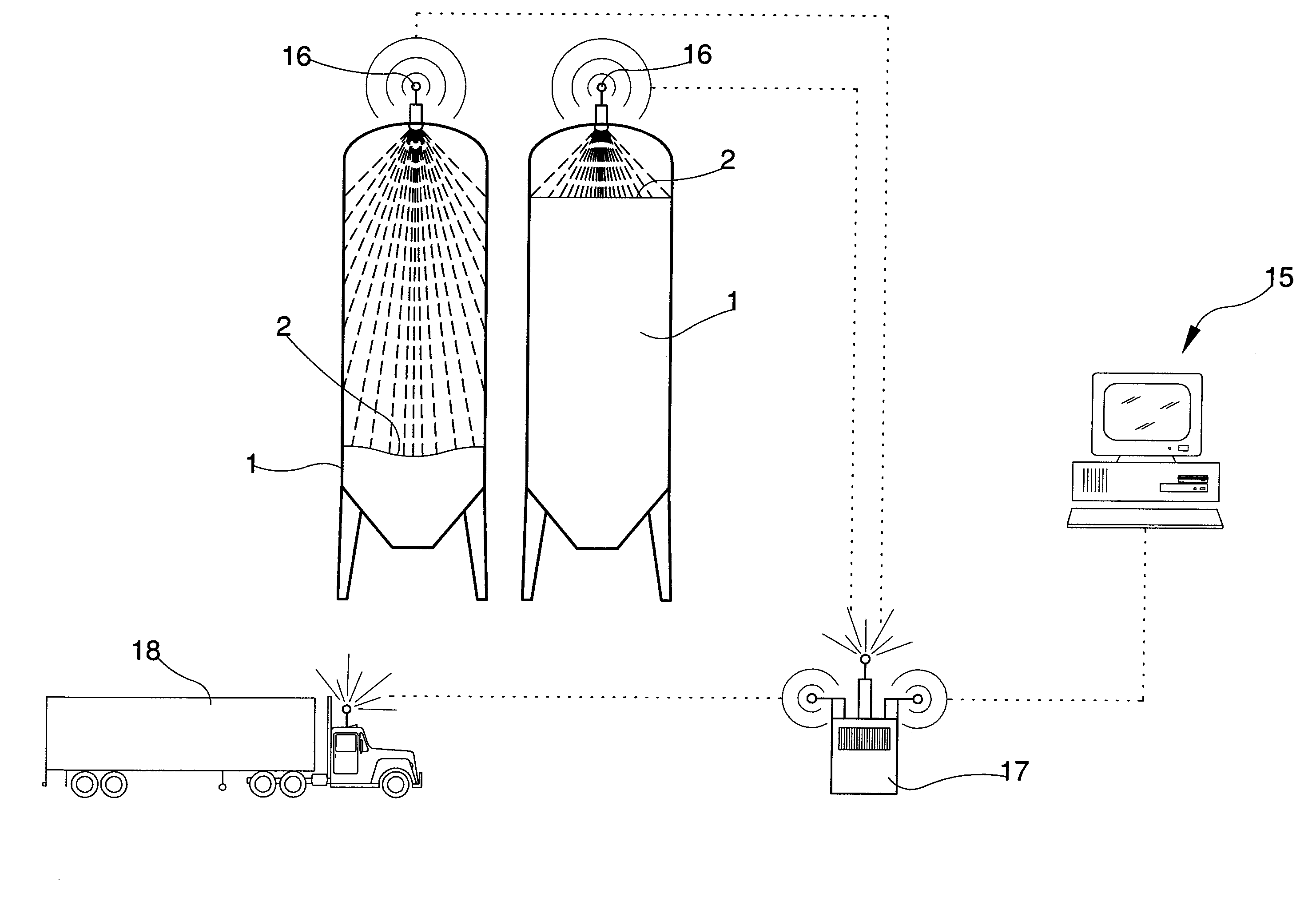
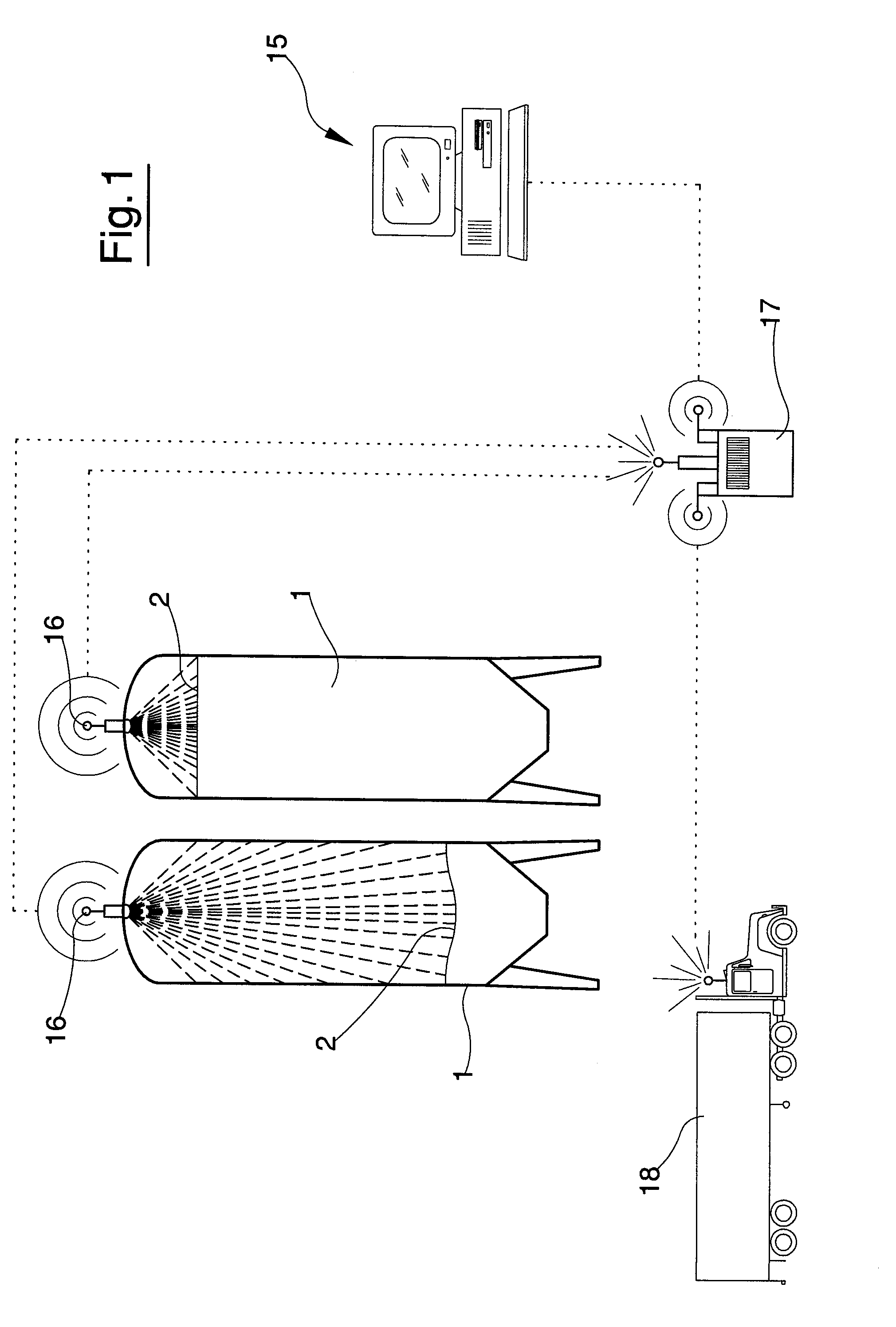
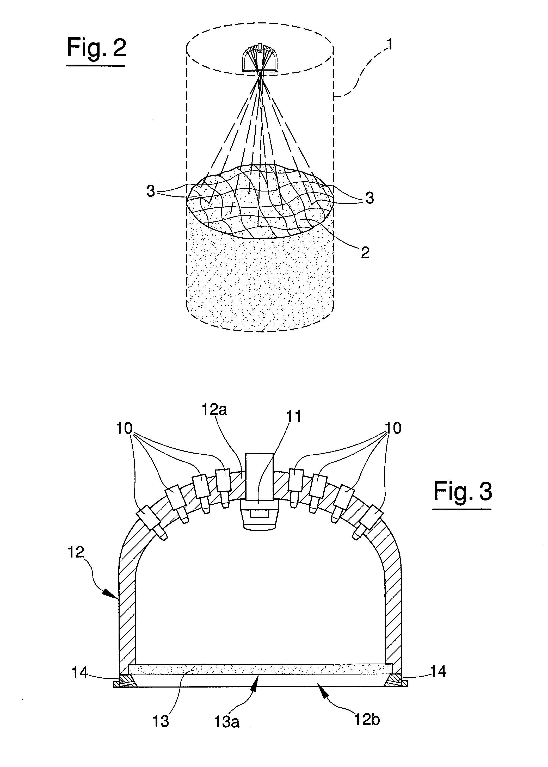
[0018]The process of the invention verifies the state of filling of a silo 1 containing loose materials, such as powders, granules, and the like; in particular the free surface 2 of the material contents in the silo can be assessed and virtually reproduced.

[0019]In a first stage the process evidences, in a way that can be read by known-type instruments, a plurality of points 3 of the free surface 2 of the material contained in the silo. To highlight some points 3 of the surface 2 a laser light beam is sent onto the surface 2, and when it hits the surface a light point 3 is obtained on the surface. For reasons that will be more fully clarified herein below, each laser beam has a predetermined direction; in other words, each laser beam is directed with a known inclination to the vertical. The laser beams which generate the points 3 are sent onto the surface 2 from above in the silo; for this purpose the devices generating the laser beams are arranged on the top part of the silo and fa...


PUM


Abstract

The process comprises a stage of highlighting a plurality of light points of a free surface of the material contained in the silo, of detecting a position of each of the light points and obtaining electrical signals which are proportional to the detected position of each point, and processing the signals to obtain a virtual reproduction of the free surface of the material which when processed provide desired data. The device for realising the process comprises lasers, which project a laser beam towards the free surface of the material contained in the silo, an optical sensor which detects the position of the light points defined by each laser beam on the free surface, and a data processing system which processes the data relating to the position of the lasers, the inclination of the laser beams, and the detected positions of the light points in such a way as to construct a virtual free surface of the material.

Description

BACKGROUND OF THE INVENTION[0001]The invention relates in particular to checking a state of filling, i.e. a level of a material, and the shape of the upper surface of the material too, in silos containing powder or granule materials used in the building, food and chemical industries and in general all those industries which use loose materials by removing them from silos where they are stored in great quantities.[0002]In silos the material is generally loaded from above, to fill the silo, and is later removed from below through special valves through which the material is removed, generally by gravity.[0003]One of the requirements of these silos is that it must always be known as closely as possible how much material is in the silo. This represents the basic information needed in order correctly to order a correct amount of material so that the silo never empties, a situation that would have obvious negative repercussions on the productive processes requiring the materials. As most ...

Claims


Application Information

Patent Timeline
IPC IPC(8): G01B11/25G01B11/22
CPCG01B11/2513G01F23/292G01F23/2928
Inventor MARCHESINI, VAINERPASSERINI, MASSIMO
Owner WAM SPA
Why Eureka
Try Eureka