Apparatus and method for detecting signal in multiple-input multiple-output (MIMO) wireless communication system

a wireless communication system and receiver technology, applied in diversity/multi-antenna systems, polarisation/directional diversity, amplitude demodulation, etc., can solve the problem of high data rate, high computational complexity of ml methods, and inability to provide good performance. , to achieve the effect of low complexity

Active Publication Date: 2008-12-18
SAMSUNG ELECTRONICS CO LTD +1
View PDF2 Cites 42 Cited by
  • Summary
  • Abstract
  • Description
  • Claims
  • Application Information

AI Technical Summary

Benefits of technology

[0012]To address the above-discussed deficiencies of the prior art, it is a primary aspect of the present invention to address at least the above mentioned problems and / or disadvantages and to provide at least the advantages described below. Accordingly, an aspect of the present invention is to provide an apparatus and a method for detecting a signal with a low complexity and a performance similar to an ML method in a MIMO wireless communication system using a Spatial Multiplexing (SM) scheme.
[0013]Another aspect of the present invention is to provide an apparatus and a method for effectively generating per bit LLRs in a MIMO wireless communication system using an SM scheme.
[0015]Still another aspect of the present invention is to provide an apparatus and a method for lowering a computational complexity of a signal detection by limiting the number of symbols substituted in each phase in a MIMO wireless communication system using an SM scheme.
[0016]A further aspect of the present invention is to provide an apparatus and a method for enhancing a performance of a signal detection by replacing symbols estimated in each phase with symbols closer to the actual transmit signal in a MIMO wireless communication system using an SM scheme.
[0017]Yet a further aspect of the present invention is to provide an apparatus and a method for lowering a computational complexity by reducing the number of transmittable symbols per phase in a MIMO wireless communication system using an SM scheme.

Problems solved by technology

In particular, the demand required massive data to be transmitted at a high data rate.
The ZF and the MMSE, which are linear signal detection methods, can be implemented in a simpler structure due to low computational complexity but can not provide good performance.
However, as the number of the transmit antennas and the modulation order increase, the computational complexity of the ML method exponentially increases as well.
Thus, it is difficult to apply the ML method to a substantial system.
However, it is hard to obtain a radius of the initial sphere and implement the sphere decoding method because too much computation is required at the worst case.
With a small number of candidate groups, its performance drastically degrades.
In addition, a larger number of candidate groups raises the computational complexity.
The sphere decoding method needs many candidate groups of the detected signal to achieve sufficient performance enhancement and suffers from high computational complexity in calculating the square Euclidean distances of the candidate groups.
As discussed above, the suggested signal detection methods for the spatial multiplexing are subject to various problems.

Method used


Image

  • Apparatus and method for detecting signal in multiple-input multiple-output (MIMO) wireless communication system
  • Apparatus and method for detecting signal in multiple-input multiple-output (MIMO) wireless communication system
  • Apparatus and method for detecting signal in multiple-input multiple-output (MIMO) wireless communication system

Examples


Embodiment Construction

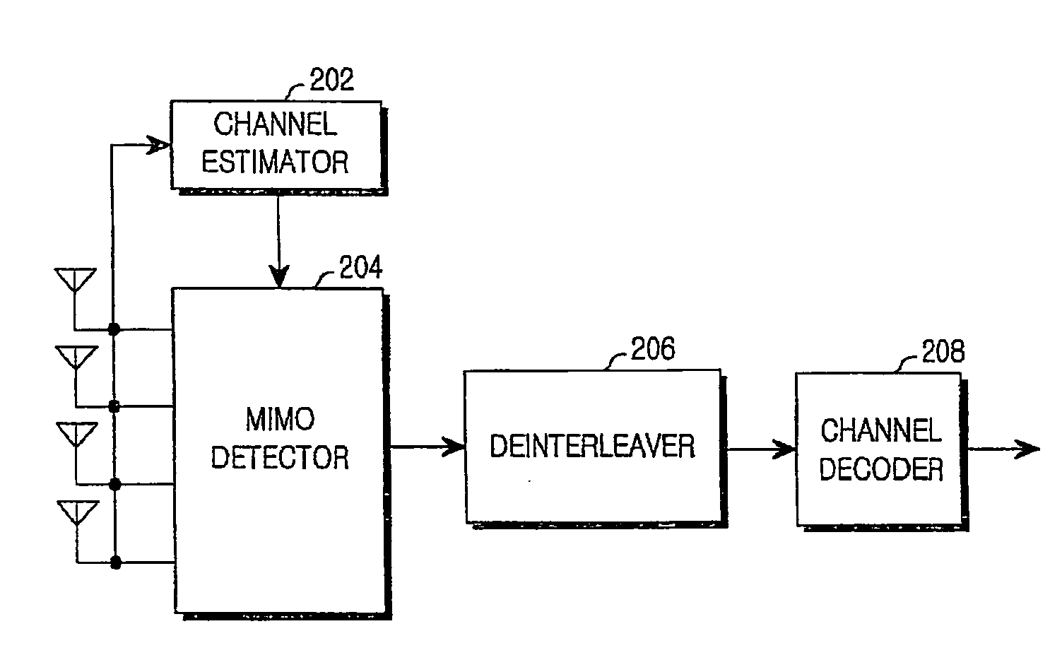
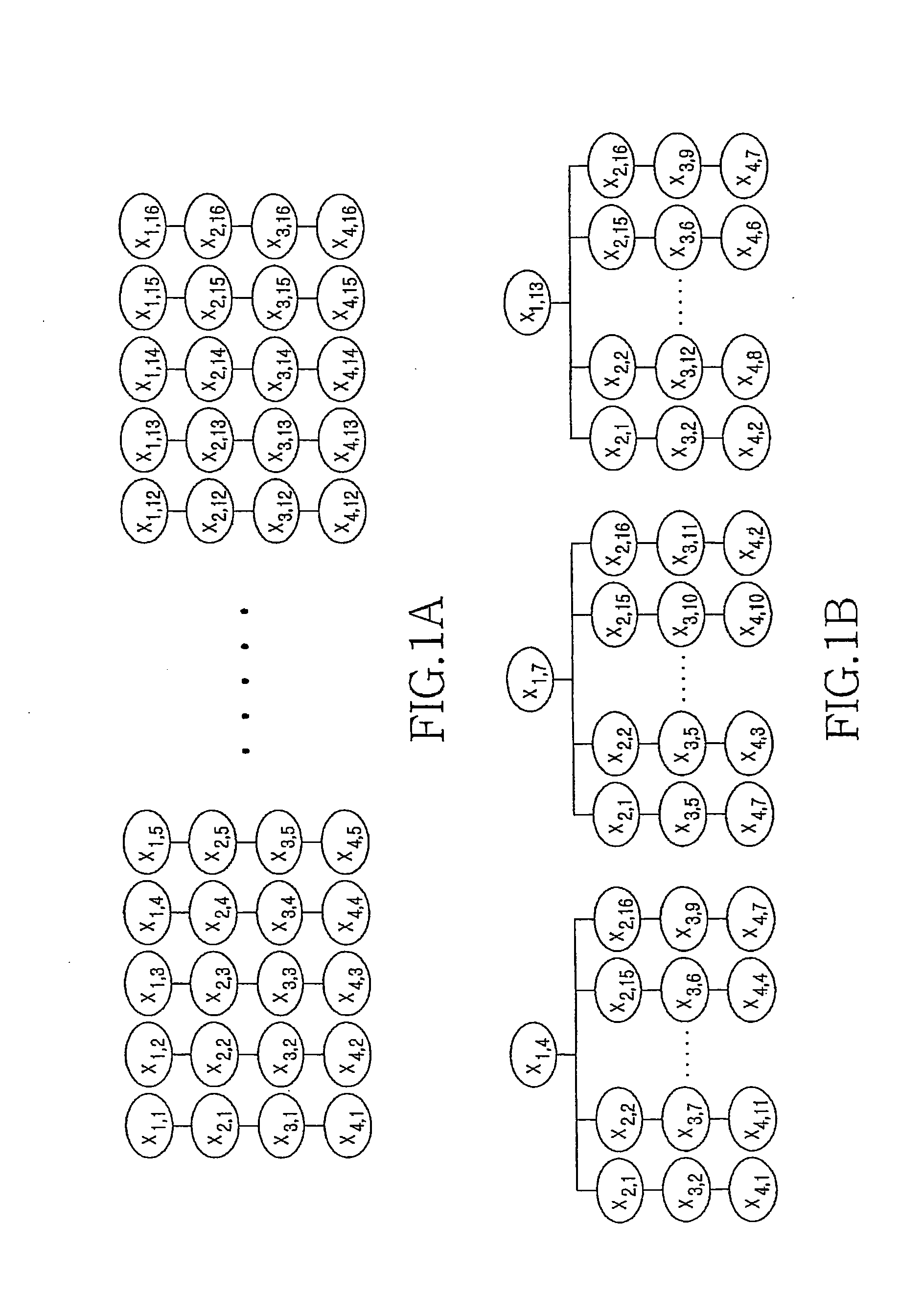
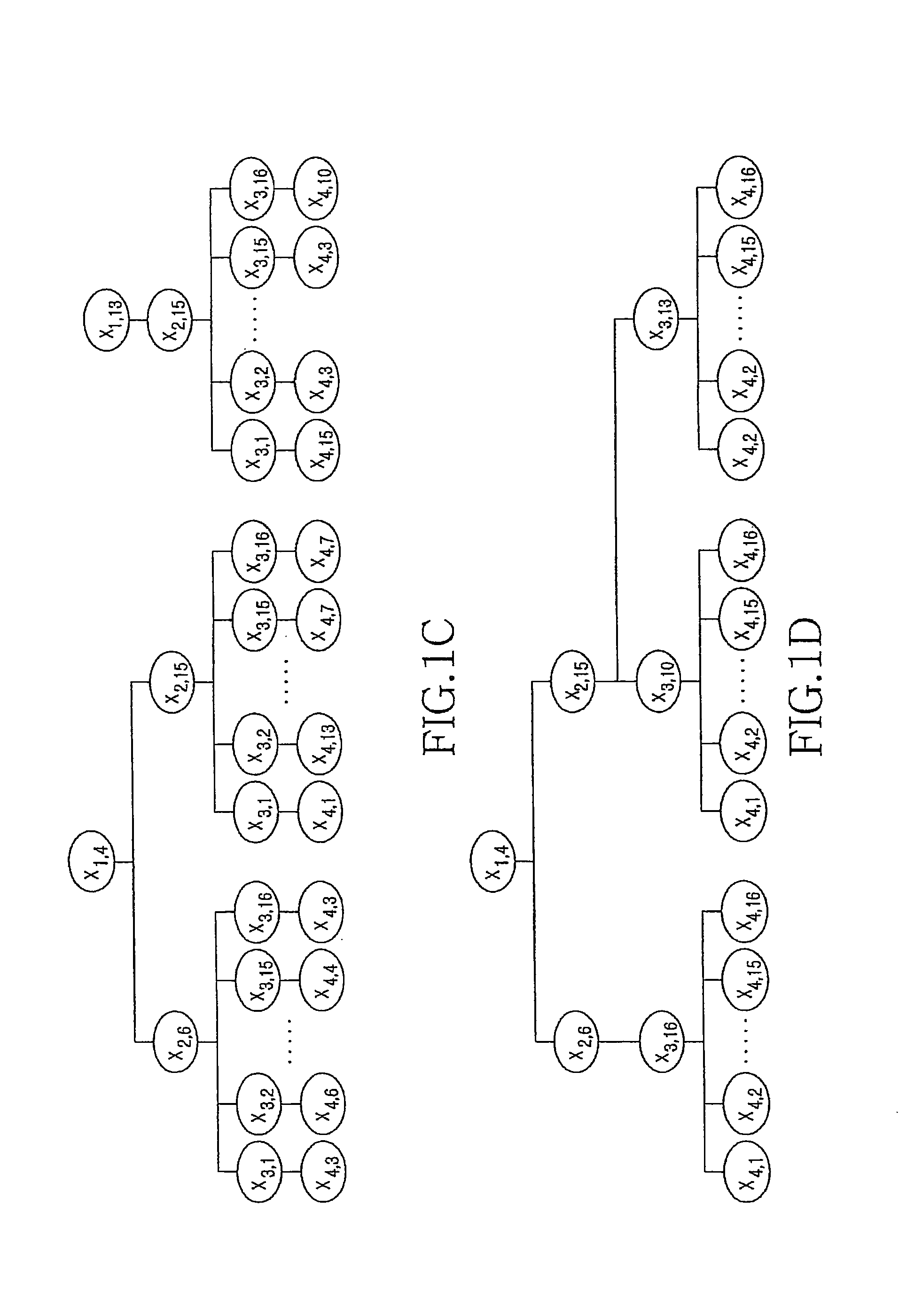
[0034]FIGS. 1A through 10B, discussed below, and the various embodiments used to describe the principles of the present disclosure in this patent document are by way of illustration only and should not be construed in any way to limit the scope of the disclosure. Those skilled in the art will understand that the principles of the present disclosure may be implemented in any suitably arranged wireless communication system.

[0035]The present invention provides a signal detecting technique with low complexity and performance similar to a Maximum Likelihood (ML) method in a Multiple-Input Multiple-Output (MIMO) wireless communication system using a Spatial Multiplexing (SM) scheme.

[0036]A channel, a transmit signal, and a receive signal between a transmitter including m-ary transmit antennas and a receiver including n-ary receive antennas are expressed as Equation 1:

H=[h11h12…h1mh21h22…h2m⋮⋮⋰⋮hn1hn2…hnm]y=Hx+ny=[y1y2…yn]Tx=[x1x2…xm]Tn=[n1n2…nn]T.[Eqn.1]

[0037]In Equation 1, xj denotes a t...


PUM


Abstract

Receiving apparatus and method in a Multiple-Input Multiple-Output (MIMO) wireless communication system are provided. The receiver having N-ary receive antennas includes a decomposer for decomposing a channel matrix to a matrix Q and a matrix R through a QR decomposition; a detector for determining a candidate group of an n-th phase by estimating a plurality of transmit signal vectors by substituting a plurality of transmittable symbols into symbol combinations of a candidate group of a (n−1)-th phase as an n-th symbol and detecting (n+1)-th through N-th symbols using characteristics of the matrix R; a calculator for calculating square Euclidean distance values between the transmit signal vectors and a receive signal vector; and a determiner for determining the candidate group of the n-th phase by selecting transmit signal vectors having the smallest square Euclidean distance value among the transmit signal vectors.

Description

CROSS-REFERENCE TO RELATED APPLICATION(S) AND CLAIM OF PRIORITY[0001]The present application claims the benefit under 35 U.S.C. §119(a) of a Korean patent application filed in the Korean Intellectual Property Office on Jun. 12, 2007 and assigned Serial No. 2007-57234, and an application filed in the Korean Intellectual Property Office on Jun. 10, 2008 and allocated Serial No. 2008-54064. The entire disclosures of both applications are hereby incorporated by reference.TECHNICAL FIELD OF THE INVENTION[0002]The present invention relates generally to a receiving apparatus and method in a Multiple-Input Multiple-Output (MIMO) wireless communication system. More particularly, the present invention relates to an apparatus and a method for detecting a signal with a performance similar to a Maximum Likelihood (ML) and with a low complexity in a MIMO wireless communication system using a Spatial Multiplexing (SM) scheme.BACKGROUND OF THE INVENTION[0003]Recent rapid growth of the wireless mobi...

Claims


Application Information

Patent Timeline
Patent Type & Authority Applications(United States)
IPC IPC(8): H04L27/06
CPCH04L25/067H04L27/38
Inventor LEE, JOO-HYUNYUN, SANG-BOHKWON, YOUNG-HOONCHOI, SOONG-YOONCHO, YONG-SOOIM, TAE-HOKIM, JAE-KWON
Owner SAMSUNG ELECTRONICS CO LTD
Why Eureka
Try Eureka