Variable geometry gas turbine engine nacelle assembly with nanoelectromechanical system

a gas turbine engine and nanoelectromechanical technology, applied in the direction of liquid fuel engines, machines/engines, efficient propulsion technologies, etc., can solve the problems of reducing efficiency, reducing noise generation, and reducing efficiency

Inactive Publication Date: 2008-12-18
UNITED TECH CORP
View PDF30 Cites 18 Cited by
  • Summary
  • Abstract
  • Description
  • Claims
  • Application Information

AI Technical Summary

Benefits of technology

[0008]A nacelle assembly includes an inlet lip section and a cowl section positioned downstream of the inlet lip section. At least a portion of the cowl section includes a flexible portion which is selectively movable to influence an effective boundary layer thickness of the nacelle assembly. A controller identifies an operability condition and selectively flexes the cowl section in response to the operability condition. The flexible portion is selectively driven by a nanoelectromechanical system

Problems solved by technology

Also, controlling the fan section tip speed allows the fan section to be of a larger diameter, which further decreases noise generation.
Although effective, a compromised “thick” inlet lip section designed for a takeoff flight condition may operate at a somewhat reduced efficiency in another flight condition, such as a cruise condition which may be better served by a “thin” inlet lip section.
Furthermore, a “thick” inlet lip section may, during some flight conditions, suffer from boundary layer separation that may decrease efficiency.
These attempts, however, have proved complex, expensive and may not fully reduce the onset of boundary layer separation.

Method used


Image

  • Variable geometry gas turbine engine nacelle assembly with nanoelectromechanical system
  • Variable geometry gas turbine engine nacelle assembly with nanoelectromechanical system
  • Variable geometry gas turbine engine nacelle assembly with nanoelectromechanical system

Examples


Embodiment Construction

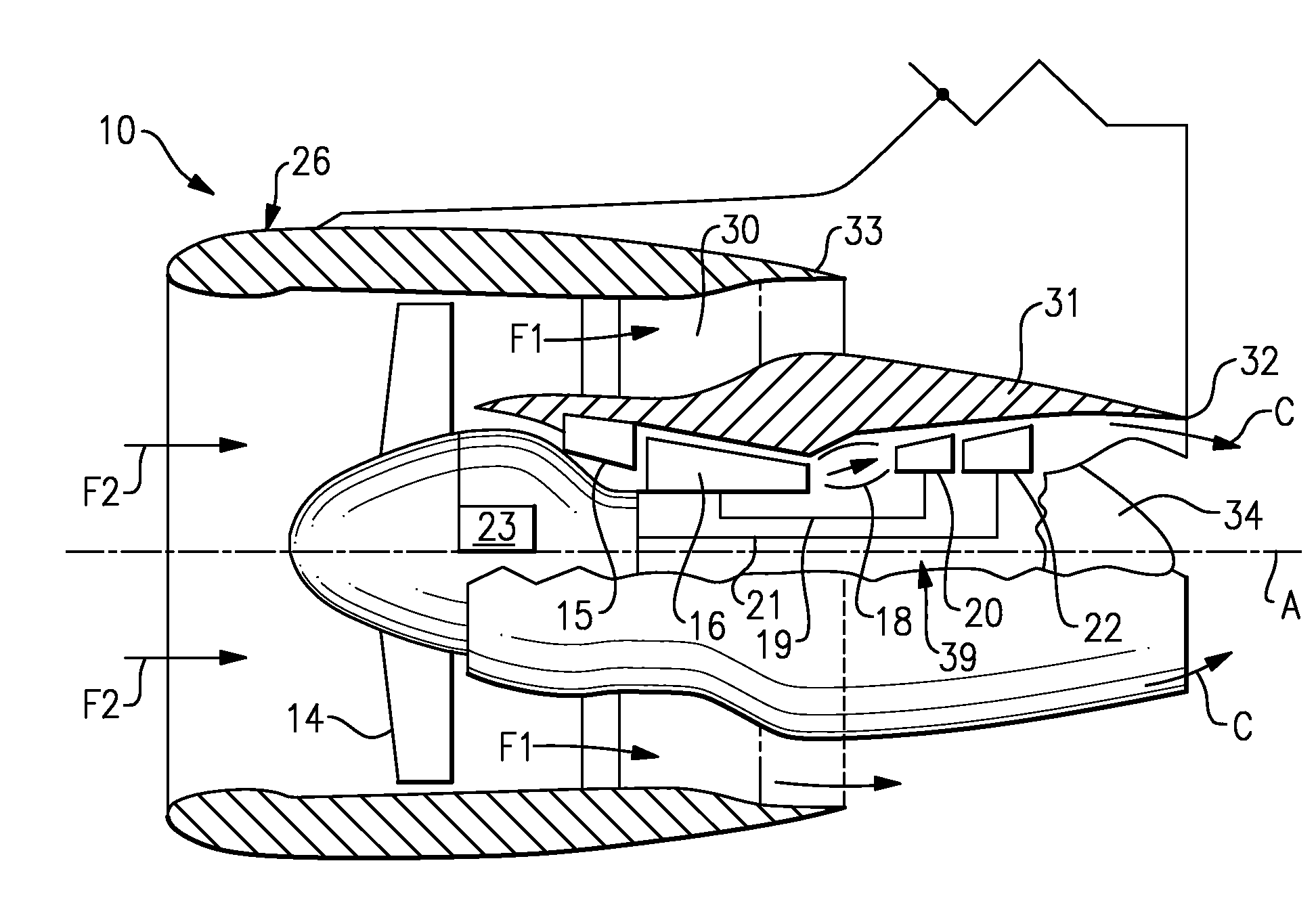
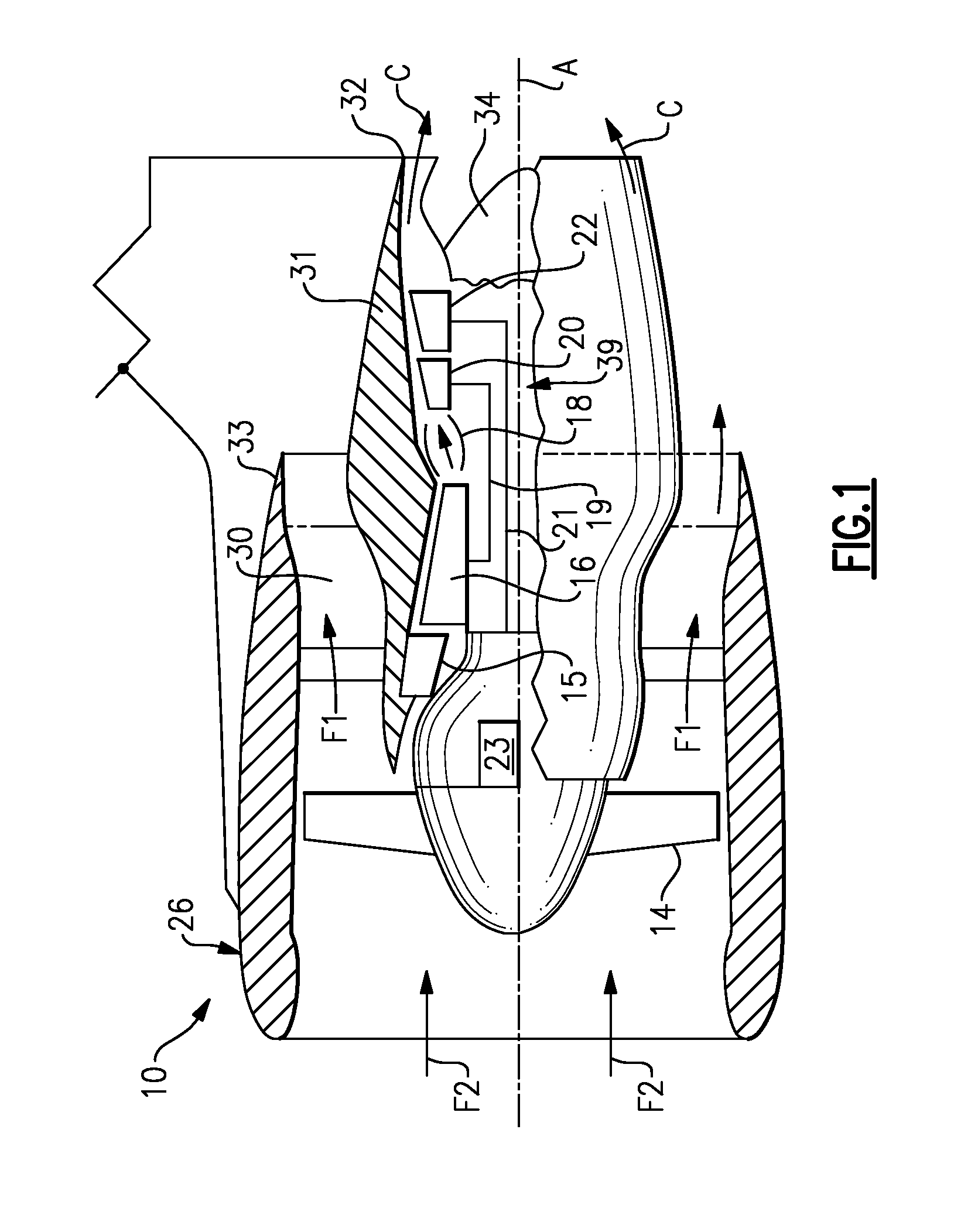
[0021]FIG. 1 illustrates a gas turbine engine 10 which includes a fan section 14, a low pressure compressor 15, a high pressure compressor 16, a combustor 18, a high pressure turbine 20, and a low pressure turbine 22. During operation, air is pressurized in the compressors 15, 16 and mixed with fuel in the combustor 18 to generate hot combustion gases. During operation, air enters the fan section 14, is pressurized by the compressors 15, 16, and is mixed with fuel and burned in a combustor 18. Hot combustion gases generated within the combustor 18 flow through the high and low pressure turbines 20, 22, which extract energy from the hot combustion gases.

[0022]In a two-spool design, the high pressure turbine 20 utilizes the extracted energy from the hot combustion gases to power the high pressure compressor 16 through a high speed shaft 19, and a low pressure turbine 22 utilizes the energy extracted from the hot combustion gases to power the low pressure compressor 15 and the fan sect...


PUM


Abstract

A nacelle assembly includes an inlet lip section and a cowl section downstream of the inlet lip section. At least a portion of the cowl section is flexed to take various shapes through a nanoelectromechanical system and thereby influence an effective boundary layer thickness of the nacelle assembly.

Description

BACKGROUND OF THE INVENTION[0001]This invention generally relates to a gas turbine engine, and more particularly to a nacelle assembly for a turbofan gas turbine engine.[0002]In an aircraft gas turbine engine, such as a turbofan engine, air is pressurized in a compressor and mixed with fuel in a combustor for generating hot combustion gases. The hot combustion gases flow downstream through turbine stages which extract energy from the hot combustion gases.[0003]Combustion gases are discharged from the turbofan engine through a core exhaust nozzle while fan air is discharged through an annular fan exhaust nozzle defined at least partially by a nacelle assembly which surrounds the core engine. A majority of propulsion thrust is provided by the pressurized fan air which is discharged through the fan exhaust nozzle, while the remaining thrust is provided from the combustion gases discharged through the core exhaust nozzle.[0004]The fan section of the turbofan engine may be geared to cont...

Claims


Application Information

Patent Timeline
Patent Type & Authority Applications(United States)
IPC IPC(8): F01D25/24
CPCB64D33/02B82Y15/00F02C7/042F02C7/045F02K3/06Y02T50/671F05D2270/62F05D2300/505Y02T50/60
Inventor JAIN, ASHOK K.
Owner UNITED TECH CORP
Why Eureka
Try Eureka