
Low-drag fin and foil system for surfboards

a foil system and surfboard technology, applied in the field of surfboards, to achieve the effect of greater acceleration and stability

Active Publication Date: 2008-12-18
MEAD TOM D
View PDF10 Cites 11 Cited by
  • Summary
  • Abstract
  • Description
  • Claims
  • Application Information

AI Technical Summary

Benefits of technology

[0036]An advantage of the present invention is that the inventive shaping of the fin members and arrangement of such on a surfboard provide greater acceleration and stability, particularly during turning maneuvers.
[0037]Another advantage of the present invention is that the shaping of the fin members and the placement of fins on the surfboard may be adjusted to conform to the parameters of the individual user, including weight, balance and typical movement speed.
[0038]These and other objects and advantages of the various embodiments of the invention will be better understood with the context provided by the detailed description of invention, and upon viewing the drawings.

Problems solved by technology

Knowledge is still very limited, however, as to how the side-fins enhance the speed and maneuverability of modern multi-finned type boards.
This has long been a major problem in surfboard design.
As a result, the first, largely experimental “twin-fin” and “fish” style surfboards, the double-finned predecessors of the modern tri-fin, suffered for many years from a variety of poorly understood control problems.
Although this eliminated the original tracking problem, it also caused an overly loose, drifting type of turn that many riders, even at the expert level, found very difficult to control.
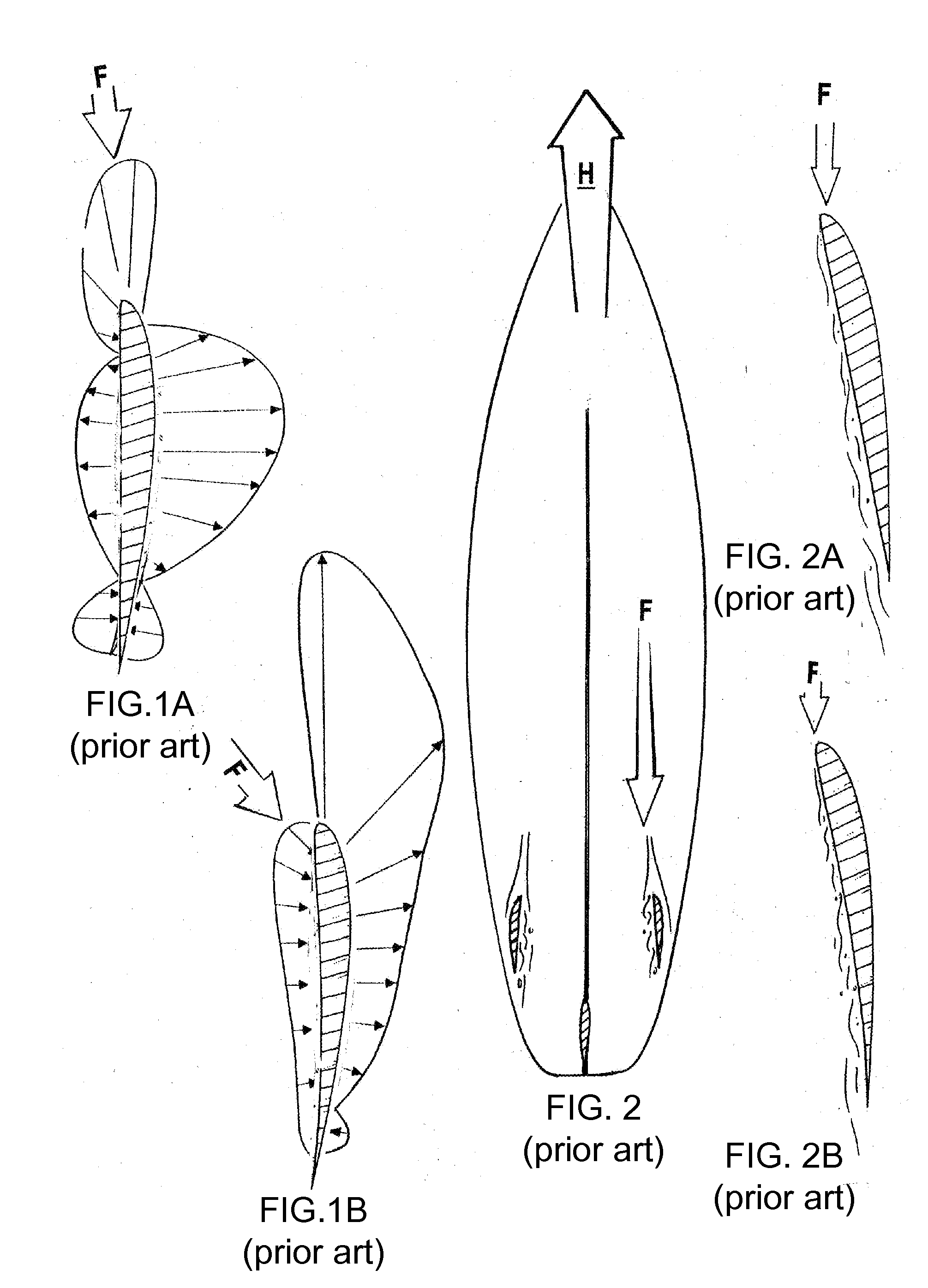
The negative angle of attack or toe-in causes the water-flow to strike the side-fins at an angle, and creates high drag from the “snowplow” effect when the rider's weight is neutrally centered on the board.
Although the cambered side-fin foil appears to give better performance and greater average speed, knowledge is currently very limited as to the reasons why, since both the flat-sided, and particularly the slightly concave side-fin foil, would appear to greatly increase the drag from the negative toe-in angle.
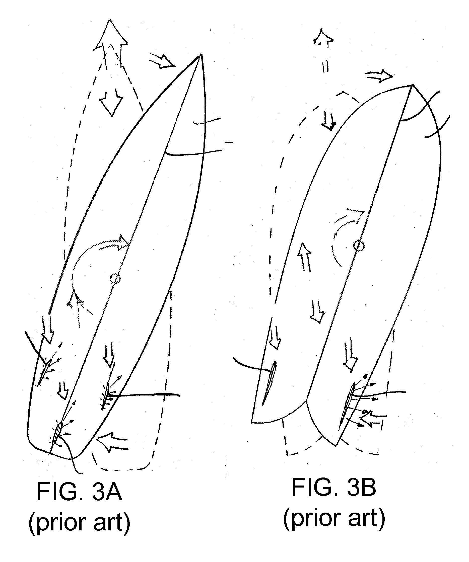
3) The location of the center stabilizing fin is precisely the opposite of the optimum theoretical configuration: i.e., if the negatively angled side-fin functions as a deflected rudder, it should be placed as far behind the board's axis of rotation as possible so as to increase its moment arm; the added leverage would lessen the surface area of the side-fin and the amount of negative toe-in angle required for a given turning moment, and thereby reduce drag. Locating the fin or fins required for directional stability forward of a negatively angled trailing fin, closer to the axis of rotation, would increase the directional instability of the fin-setting by allowing the negatively angled rearward fin to truly function as a permanently deflected rudder. Failure to correct the drawbacks outlined above, and the absence of innovation regarding fin placement on multi-fin type boards (the group includes other multi-finned variants, e.g., “twinzers,”” quads,”“fishes,” etc. all of which use the negatively angled side-fin setting), is largely due to the poor understanding of the role the fins play in enhancing the performance of the board. Despite the high speed and exceptional maneuverability of modern multi-finned boards vs. the early single-finned board types, at present, their higher performance actually comes at a cost of considerable drag. From a hydrodynamic standpoint, it can be seen that the board-making arts currently have need of a cambered side-fin foil that exhibits reduced drag at the conventional negatively angled side-fin setting, as well as multi-fin arrangements that will introduce directional instability, but at a reduction in drag over the multi-fin configurations of the prior art.
Those skilled in the art, however, will be aware of the current lack of tank-testing facilities, and the absence of any method that can accurately duplicate a breaking wave, the movement of the board on a wave, or the effects of the rider maneuvering the board in a controlled setting.

Method used


Image

  • Low-drag fin and foil system for surfboards
  • Low-drag fin and foil system for surfboards
  • Low-drag fin and foil system for surfboards

Examples


Embodiment Construction

therefore begins with a discussion of the relationship between the (hydro-) foil of the fin, and the airfoils of a wing and a sail, which respond in similar ways to a fluid flow despite the differing densities between air and water. The improved fin foils and multi-fin configurations of the present invention are based on an analysis of how the angle of attack an individual fin can be combined with a secondary fin at a different angle to dramatically improve the speed and performance of multi-finned boards. This involves two closely related premises, which are summarized briefly as follows:

[0012]The rotation of the board as it is turned places the fin(s) at a high angle of attack relative to the water flow resulting from the board's original heading; when a fin foil having a high lift coefficient is placed at a high angle of attack to a water flow, it develops an area of very low pressure around its leading edge similar to the low-pressure area known to develop around the forward por...


PUM


Abstract

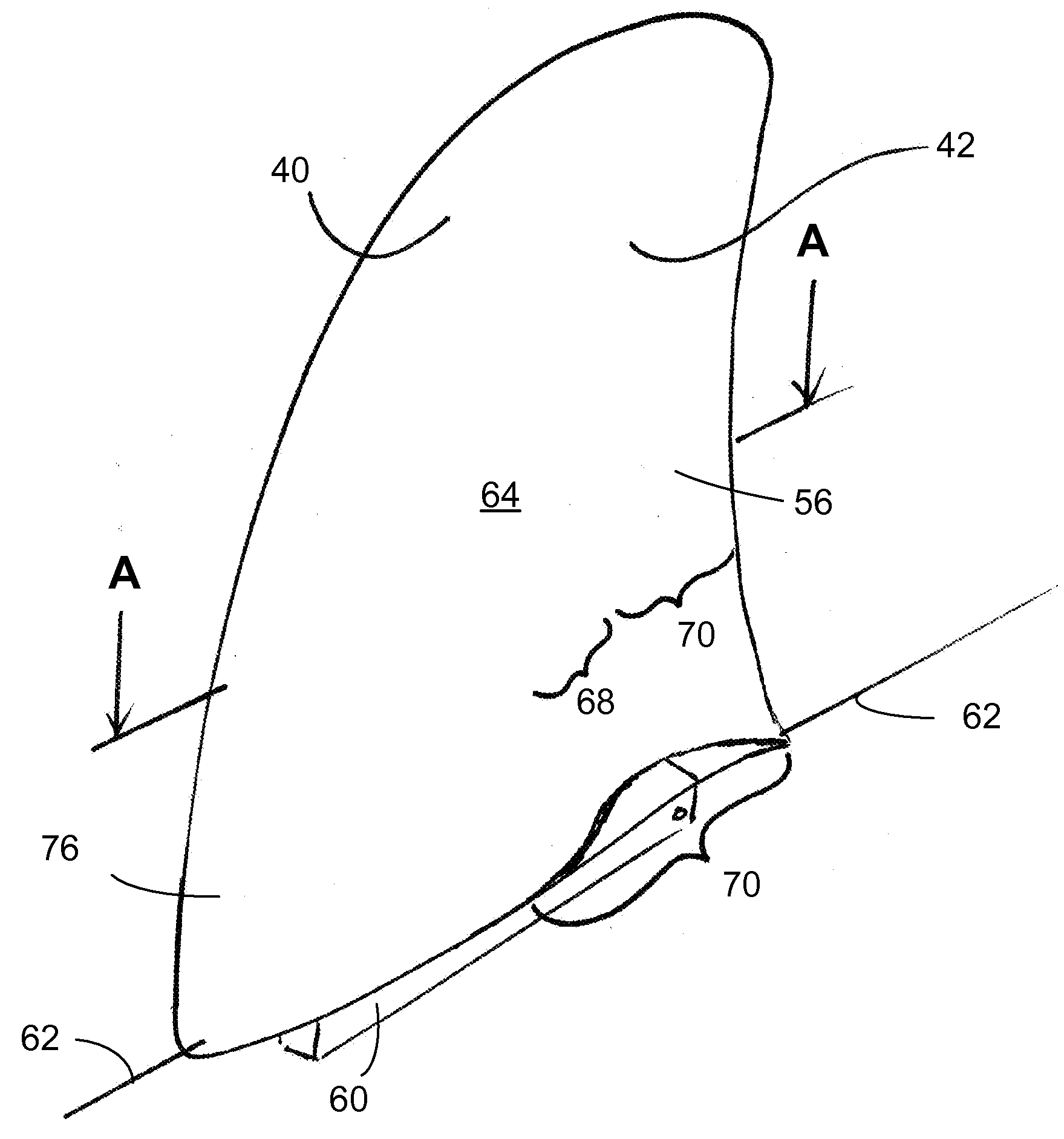
The present invention is a Low-Drag Fin and Foil System for Surfboards (10), particularly including cambered fin foils (40; 42). The invention (10) also discloses low-drag, directionally unstable fin positions wherein the lesser of negative angle of attack of a trailing fin (50), versus the higher or positive angle of attack of a forward fin (48), makes the board (12) highly maneuverable by creating a yawing moment that aids the rotation of the board (12) as it is turned. The system particularly utilizes fins (40) having foil (42) shapes in which either the cambered side (74) or the non-cambered side (76) is provided with a combination of a convex curvature (68) and a concave curvature (70) to result in an oscillating curvature (72) which has a positive effect on control and acceleration.

Description

RELATED APPLICATION[0001]This application claims priority from International Application Number PCT / US2005 / 045791, which, in turn, claims priority from U.S. Provisional Application No. 60 / 637,299 filed 17 Dec. 2004 by the same inventor.TECHNICAL FIELD[0002]This invention relates to surfboards, and more particularly to the foil of the fin on multi-fin type boards, and to the positioning of the fins on the bottom of the board.BACKGROUND ART[0003]Prior to the initial experimentation with double-finned surfboards in the early 1970's, a single center fin, located at the very tail of the board, provided the directional stability essential to the basic performance of the board. Since the advent of tri-fin or “thruster” type surfboards in the early 1980's, high-performance surfboards have also incorporated two side-fins to dramatically increase the board's speed and maneuverability. The side-fins are located on opposite sides of the board near the perimeter edge or “rail,” and well forward ...

Claims


Application Information

Patent Timeline
Patent Type & Authority Applications(United States)
IPC IPC(8): B63B35/79
CPCB63B35/7926B63B39/06B63B35/79B63B32/60
Inventor MEAD, KIRBY J.
Owner MEAD TOM D
Learn More