Internal combustion engine intake gate and exhaust gate control method

An internal combustion engine intake and exhaust, intake valve technology, applied in engine control, internal combustion piston engine, combustion engine and other directions, to achieve the effect of improving startability, improving power and economy, and reducing emissions

Inactive Publication Date: 2012-05-09
DALIAN UNIV OF TECH
View PDF7 Cites 11 Cited by
  • Summary
  • Abstract
  • Description
  • Claims
  • Application Information

AI Technical Summary

Problems solved by technology

[0007] The object of the present invention is to solve the problems in the above-mentioned internal combustion engine research field, and utilize a variable valve drive system to realize two driving modes of high compression ratio and low expansion ratio or low compression ratio and high expansion ratio on a turbocharged internal combustion engine, so as to achieve an overall increase in turbocharging. The low-speed high-torque working condition of the compressed internal combustion engine and the dynamic performance of the plateau working condition improve the startability, acceleration and high-speed performance; the variable valve drive system is used to realize different braking conditions on the naturally aspirated internal combustion engine and the turbocharged internal combustion engine. Braking mode, in order to change the 720° / cycle internal combustion engine into a 360° / cycle compressor, replace the vehicle auxiliary braking system to achieve internal combustion engine braking, and adjust the opening parameters of the valve to achieve the purpose of adjustable braking effect

Method used


Image

  • Internal combustion engine intake gate and exhaust gate control method
  • Internal combustion engine intake gate and exhaust gate control method
  • Internal combustion engine intake gate and exhaust gate control method

Examples


Embodiment Construction

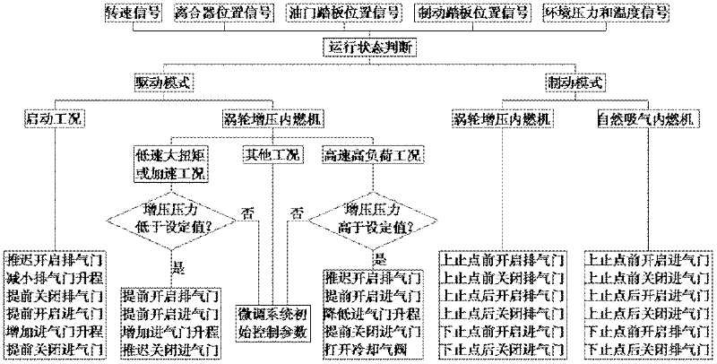
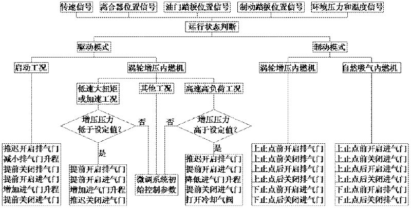
[0020] figure 1It is a schematic diagram of an internal combustion engine intake and exhaust valve control method. The specific control method is as follows: through the real-time detection of internal combustion engine performance parameters (mainly the internal combustion engine speed signal, clutch position signal, accelerator pedal position signal, brake pedal position signal, etc.), it is judged whether the current internal combustion engine operating condition is the driving mode or the braking mode. model. The valve control method of the invention is based on the opening and closing parameters of the intake and exhaust valves of the turbocharged internal combustion engine adopting the variable intake valve system.

[0021] (1) If it is the drive mode, first judge whether it is in the start-up condition, and then for the turbocharged internal combustion engine, continue to judge whether the current operating condition is in the low-speed and high-load condition or the h...


PUM


Abstract

The invention relates to an internal combustion engine intake gate and exhaust gate control method, belonging to the fields of internal combustion engine intake and exhaust systems and brake. In the control method, two drive modes of high compression ratio and low expansion ratio or low compression ratio and high expansion ratio, and a brake mode of air intake from the intake gate and air exhaustfrom the exhaust gate of a turbocharging internal combustion engine, and a brake mode of a naturally aspirated internal combustion engine are proposed, so as to achieve the control method of the intake gate and exhaust gate in these modes. By using the high compression ratio and low expansion ratio mode for low speed and high torque, tableland environment and acceleration condition, and low compression ratio and high expansion ratio mode for high speed and heavy load condition of the turbocharging internal combustion engine, in combination, the dynamic property, accelerating ability and high speed performance for low speed and high torque and tableland condition are simultaneously improved. By using the brake mode to convert the internal combustion engine with 720 degree per cycle to an air compressor with 360 degree per cycle, an auxiliary brake system of a vehicle is replaced, thus the brake of the internal combustion engine is realized, and the effect of adjustable brake by regulation of the starting parameters of air gates is realized.

Description

technical field [0001] The invention relates to a method for controlling the intake and exhaust valves of an internal combustion engine, so as to realize two driving modes of a turbocharged internal combustion engine, high compression ratio and low expansion ratio or low compression ratio and high expansion ratio, and the braking of forward as forward and exhaust as exhaust Mode, the intake and exhaust valve events required by the braking mode of a naturally aspirated internal combustion engine, belongs to the field of intake and exhaust systems and braking of internal combustion engines. Background technique [0002] On the one hand, with the sharp increase in the number of internal combustion engines, the continuous rise of world oil prices, and the increasingly serious air pollution, the problem of how to effectively improve the efficiency of internal combustion engines and reduce emissions has become increasingly urgent. Turbocharged internal combustion engines have high ...

Claims


Application Information

Patent Timeline
Patent Type & Authority Applications(China)
IPC IPC(8): F01L13/06F02D13/04F01L9/04F01L1/34F01L9/10
CPCY02T10/18Y02T10/12
Inventor 隆武强崔靖晨盛凯田江平冷先银齐鲲鹏董全张强
Owner DALIAN UNIV OF TECH
Why Eureka
Try Eureka