Method and system for controlling a valve device

a valve device and valve body technology, applied in the direction of valve operating means/release devices, electric control, machines/engines, etc., can solve the problems of difficult throttle plate positioning, low response time required for throttle valve positioning in such etc. systems, and rarely use the maximum available motor control voltage, etc., to achieve optimal use of actuator control voltage, reduce the response time of such valve devices, and enhance acceleration

Inactive Publication Date: 2009-06-23
GM GLOBAL TECH OPERATIONS LLC
View PDF18 Cites 11 Cited by
  • Summary
  • Abstract
  • Description
  • Claims
  • Application Information

AI Technical Summary

Benefits of technology

[0011]The feedforward control signal is characterized by a voltage that is adjusted to cause the estimated velocity of the movable valve member to approximately follow a defined maximum deceleration velocity trajectory as the estimated position moves to the desired position. Preferably, the voltage of the feedforward signal comprises a predetermined maximum voltage, which is adjusted in accordance with a defined saturation function that varies based upon the desired position signal, the simulated position signal, and the simulated velocity signal. The predetermined maximum voltage for the feedforward control signal is selected to utilize a substantial portion of available actuator control voltage to enhance the acceleration and deceleration of the throttle plate in controlling the estimated velocity without causing saturation of the motor control signal.
[0012]Accordingly, the invention provides for more optimal use of available actuator control voltage when controlling valve devices, which significantly reduces the response time of such valve devices, without introducing additional overshoot and settling time.
[0013]According to another aspect of the invention, a compensation signal is generated based upon the actual position signal, and a simulated compensation signal is generated based upon the simulated position signal. The compensation signal is then combined with the feedback control signal to produce the actuator control signal, and the simulated compensation signal is combined with the feedforward control signal to produce the simulated actuator control signal. In this way, the actuator control signal and simulated actuator control signal can be compensated to offset torque opposing movement of the movable valve member caused by frictional and / or spring biasing forces associated with the valve device and electric actuator.

Problems solved by technology

Use of the biasing springs in the electronic throttle valve generally introduces significant nonlinear spring forces, which along with other frictional forces can complicate the positioning of the throttle plate.
Due to these constraints, controllers in ETC systems rarely use the maximum available motor control voltages when generating motor control signals for controlling the electric motors.
As a consequence, the response time required for positioning of the throttle valve in such ETC systems tends to be appreciably less than optimal.

Method used


Image

  • Method and system for controlling a valve device
  • Method and system for controlling a valve device
  • Method and system for controlling a valve device

Examples


Embodiment Construction

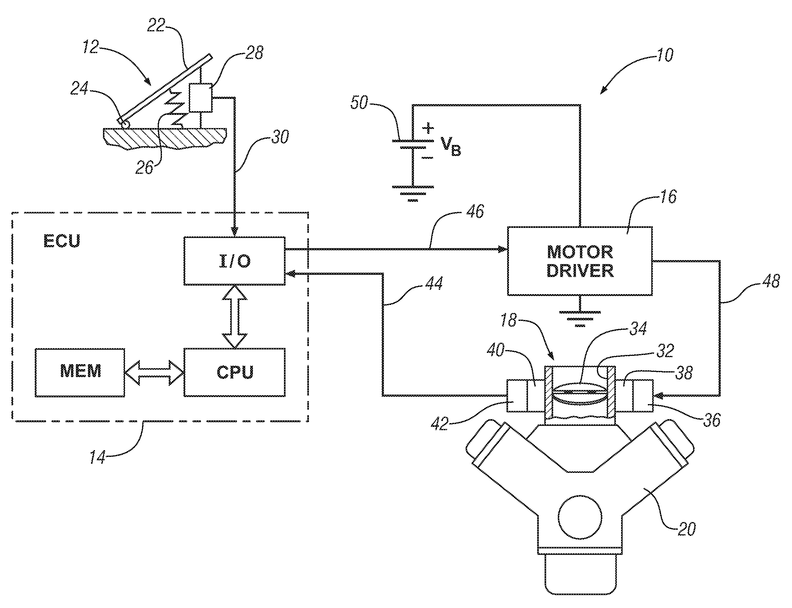
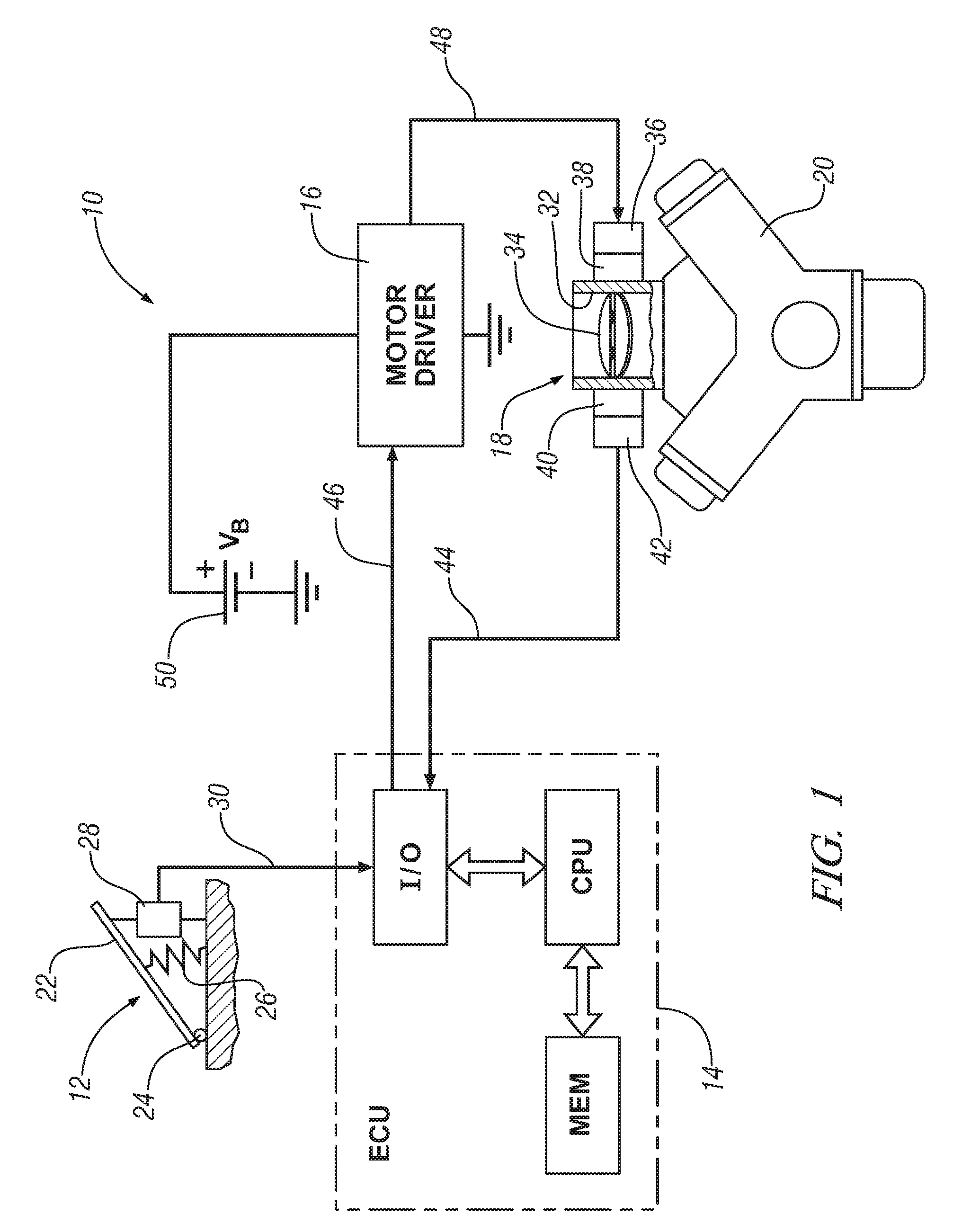
[0026]Referring now to FIG. 1, there is shown an exemplary engine control system generally designated by the numeral 10, in which the present invention may be implemented for an electronic throttle control (ETC) application. The basic components for the ETC in engine control system 10 include an accelerator pedal assembly generally designated as 12, a control unit designated here as engine control unit (ECU) 14, a motor driver 16, and an electronic throttle valve generally designated as 18 for adjusting the amount of air flowing into an engine 20. Those skilled in the art will recognize that engine control system 10 generally will include additional components that have not been shown that are typically present for controlling operational aspects of engine 20 other than ETC . The control unit 14 may also be referred to as an engine control module (ECM) or a powertrain control module (PCM) depending upon the functionality integrated into the control unit 14.

[0027]Accelerator pedal as...


PUM


Abstract

A system and method are disclosed for controlling the positioning of a movable member of a valve device by an electric actuator. A model is used to generate estimates for the position and velocity of the movable valve member that result from an actuator control signal being applied to drive the electric actuator. The actuator control signal comprises a feedback control signal combined with a feedforward control signal. The feedback control signal is generated based upon a difference between the estimated and actual positions of the movable valve member, while the feedforward control signal is generated based upon the desired position, the estimated position, and the estimated velocity. The feedforward signal is adjusted to cause the estimated velocity to approximately follow a defined maximum deceleration velocity trajectory as the estimated position of the movable valve member moves to the desired position. An exemplary embodiment is presented where the principles of the invention are applied to the control of an electronic throttle valve.

Description

TECHNICAL FIELD[0001]The present invention relates to a method and apparatus for controlling a valve device having a movable valve member positioned by an electric actuator, and more particularly, to a method and apparatus for improved control of valve devices such as electronic throttle valves and the like.BACKGROUND OF THE INVENTION[0002]Over the past several years, different control techniques have been employed for the positioning of movable valve members of valve devices utilizing electric motors. Generally, the speed and accuracy at which such valve members can be positioned is of significance. One such application where the speed and accuracy of positioning the movable valve member provides important functional advantages is in the area of electronic throttle control (ETC).[0003]Modern vehicles generally employ some type of electronic throttle control (ETC) system for positioning of the engine intake air throttle valve to achieve the benefits of reduced emissions, increased f...

Claims


Application Information

Patent Timeline
Patent Type & Authority Patents(United States)
IPC IPC(8): F02D41/14
CPCF02D11/10F02D2041/141F02D2041/1433F02D2200/0404F02D2041/1409
Inventor KRUPADANAM, ASHISH S.
Owner GM GLOBAL TECH OPERATIONS LLC
Why Eureka
Try Eureka