
Capsule Medical System

a medical system and capsule technology, applied in the field of capsule medical system, to achieve the effect of accurate estimation

Inactive Publication Date: 2008-12-18
OLYMPUS MEDICAL SYST CORP
View PDF9 Cites 81 Cited by
  • Summary
  • Abstract
  • Description
  • Claims
  • Application Information

AI Technical Summary

Benefits of technology

[0011]In such a structure, by repeatedly performing a correction process in which the estimated value of the location and / or orientation of the antenna incorporated in the capsule intracorporeal device is updated, the location and / or orientation of the antenna can be accurately estimated.

Problems solved by technology

However, Japanese Unexamined Patent Application Publication No. 2003-135389 describes neither a method of specifically detecting the location of the capsule nor a method of detecting the orientation of the capsule or the antenna in the capsule from the transmitted radio signal.

Method used


Image

  • Capsule Medical System
  • Capsule Medical System
  • Capsule Medical System

Examples


first embodiment

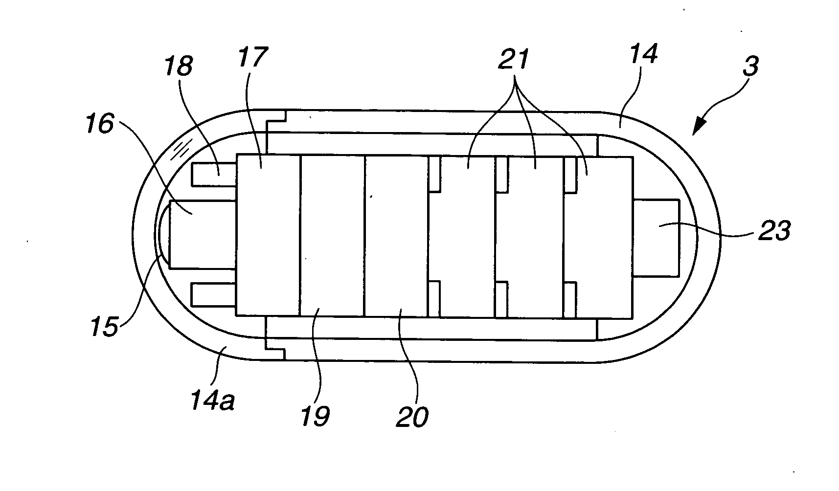
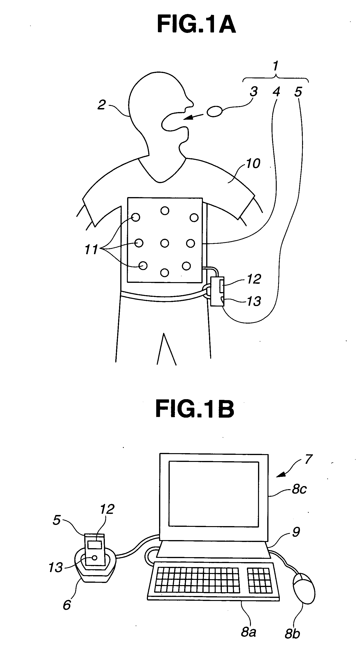
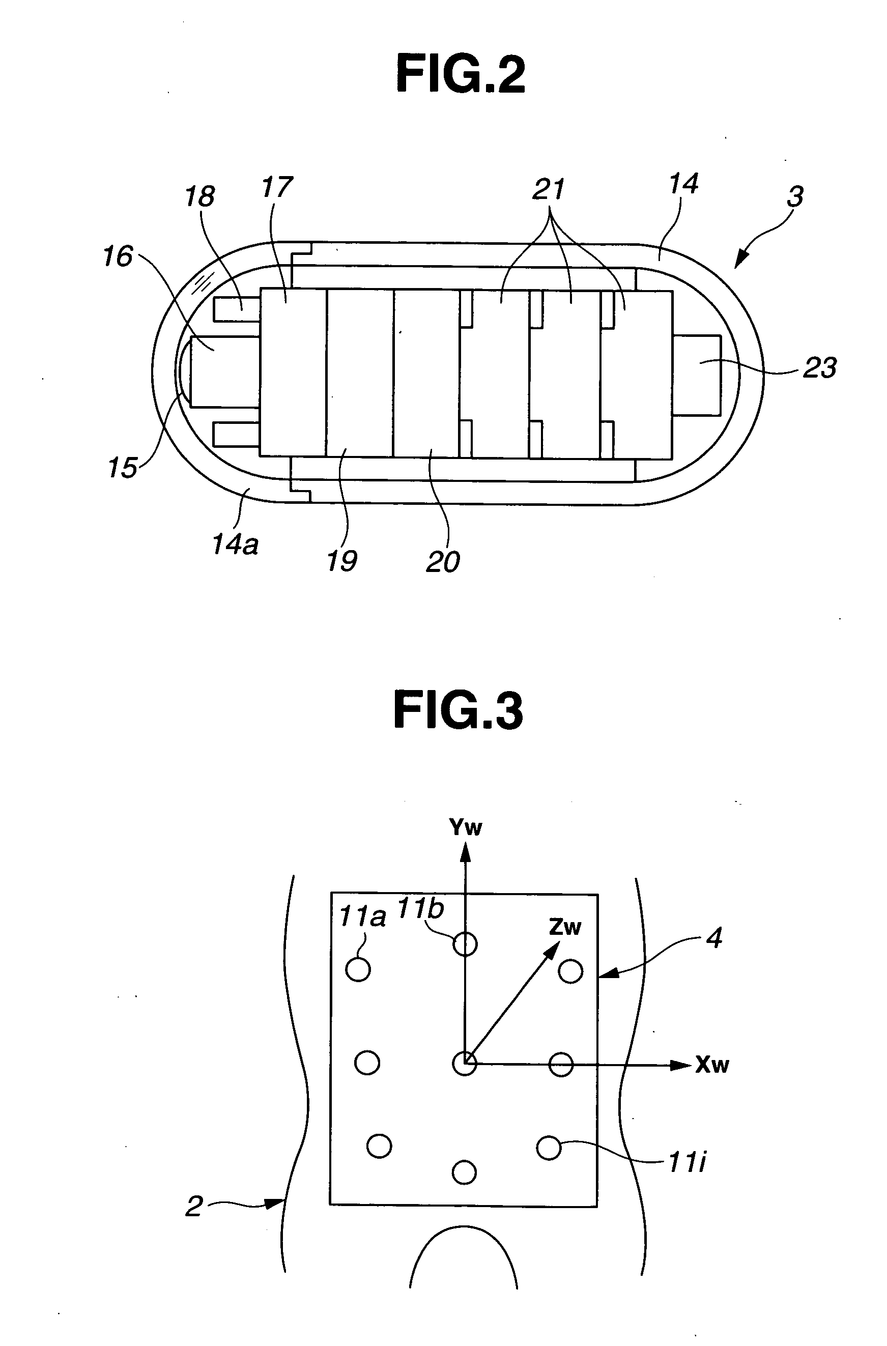
[0031]FIGS. 1A to 11 relate to a first embodiment of the present invention. FIG. 1A illustrates an exemplary main portion of a capsule medical system according to the first embodiment of the present invention. FIG. 1B illustrates an extracorporeal device shown in FIG. 1A that is connected to a data station via a cradle. FIG. 2 illustrates the internal structure of a capsule endoscope. FIG. 3 illustrates an exemplary arrangement of a plurality of antennas of an antenna unit and the coordinate system defined for the antennas. FIG. 4 is a block diagram schematically illustrating the internal structure of the capsule endoscope system shown in FIG. 1A.

[0032]FIG. 5A illustrates an example of a signal transmitted from the capsule endoscope shown in FIG. 1A during a frame period. FIG. 5B illustrates another example of the signal transmitted from the capsule endoscope shown in FIG. 1A during a frame period. FIG. 6 is a diagram illustrating a component of an electromagnetic field at a given p...

second embodiment

[0114]A second embodiment of the present invention is described next. The hardware configuration of the second embodiment is similar to that of the first exemplary embodiment. In the second embodiment, an electric field is used that takes into account the case where the endoscopic capsule 3 moves close to the antennas 11s attached to the body surface of the patient 2.

[0115]The operation of the present embodiment is described next.

[0116]When the frequency of electromagnetic field generated by the antenna 23 disposed in the endoscopic capsule 3 is high and, as shown in FIG. 1A, the distance between the endoscopic capsule 3 and the antennas 11s attached to the body surface of the patient 2 is sufficiently large, the radiation field component of the electromagnetic field that reaches the antenna 11s becomes the highest. However, if the endoscopic capsule 3 moves close to the antennas 11s, that is, if the distance between the endoscopic capsule 3 and the antennas 11s becomes small, the e...

third embodiment

[0126]A third embodiment of the present invention is described below with reference to FIG. 12. The configuration of this embodiment is described first. In the configuration of the endoscopic capsule according to this embodiment, the structure (shape) of the antennas 11 used in the antenna unit 4 differs from that used in the first embodiment.

[0127]Accordingly, the equation representing the electric field detected by the antennas 11 is different. More specifically, according to the present embodiment, a partly cut circular antenna 11 (a circular antenna that is not a closed loop) shown in FIG. 12 is employed. The other configurations are similar to those of the first embodiment.

[0128]The operation of the present embodiment is described next.

[0129]In the first exemplary embodiment, the linear dipole antenna 11 is used to detect the electric field. However, in the present embodiment, an antenna having a circularly curved shape as shown in FIG. 12 is used to detect the electric field g...


PUM


Abstract

A capsule medical system is provided that accurately detects the location at which biological information, such as an image captured in a living body, is acquired. A circular loop antenna 23 incorporated in an endoscopic capsule traveling in a living body transmits a high-frequency signal and a plurality of antennas 11a to 11i disposed on a body surface of the living body receives the signal. A CPU 36 defines the initial location and orientation of the antenna 23. The CPU then performs an estimation process on the initial location and orientation so as to compute new estimated location and orientation and update the initial location and orientation to the new location and orientation. The CPU similarly performs the estimation process on the updated location and orientation. The CPU performs accurate location estimation by repeatedly performing the estimation process until the amount of shift of the location computed and updated by the estimation process reaches a sufficiently small value.

Description

TECHNICAL FIELD[0001]The present invention relates to a capsule medical system that is placed within a living body so as to, for example, capture an image.BACKGROUND ART[0002]Endoscopes have been in widespread use in medical field and etc. by inserting an insertion portion of the endoscope into a body cavity of a patient in order to examine or treat the patient as needed.[0003]In recent years, swallowable capsule medical systems have been available that capture an image of the interior of the body cavity for inspection of the body cavity.[0004]In general, when the capsule medical system is placed in the body cavity, the capsule medical system moves in the body cavity due to the peristaltic motion. Accordingly, a user may want to know at which location in the body cavity the information from the capsule medical system is obtained.[0005]To address this issue, Japanese Unexamined Patent Application Publication No. 2003-135389, for example, describes a technology in which a plurality of...

Claims


Application Information

Patent Timeline
Patent Type & Authority Applications(United States)
IPC IPC(8): A61B1/04A61B1/00G01S5/02
CPCA61B1/00016A61B1/0005A61B1/041A61B5/06A61B5/07A61B5/6805A61B2560/0456G01S5/02G01S5/0252A61B5/062G01S5/02527G01S5/02522A61B1/00055A61B5/073G01S5/017
Inventor HASEGAWA, JUNNONAMI, TETSUO
Owner OLYMPUS MEDICAL SYST CORP
Learn More