Device and system for stabilizing movement between bony tissue and method for implanting

Inactive Publication Date: 2008-12-18
ZIMMER SPINE INC
View PDF21 Cites 36 Cited by
  • Summary
  • Abstract
  • Description
  • Claims
  • Application Information

AI Technical Summary

Benefits of technology

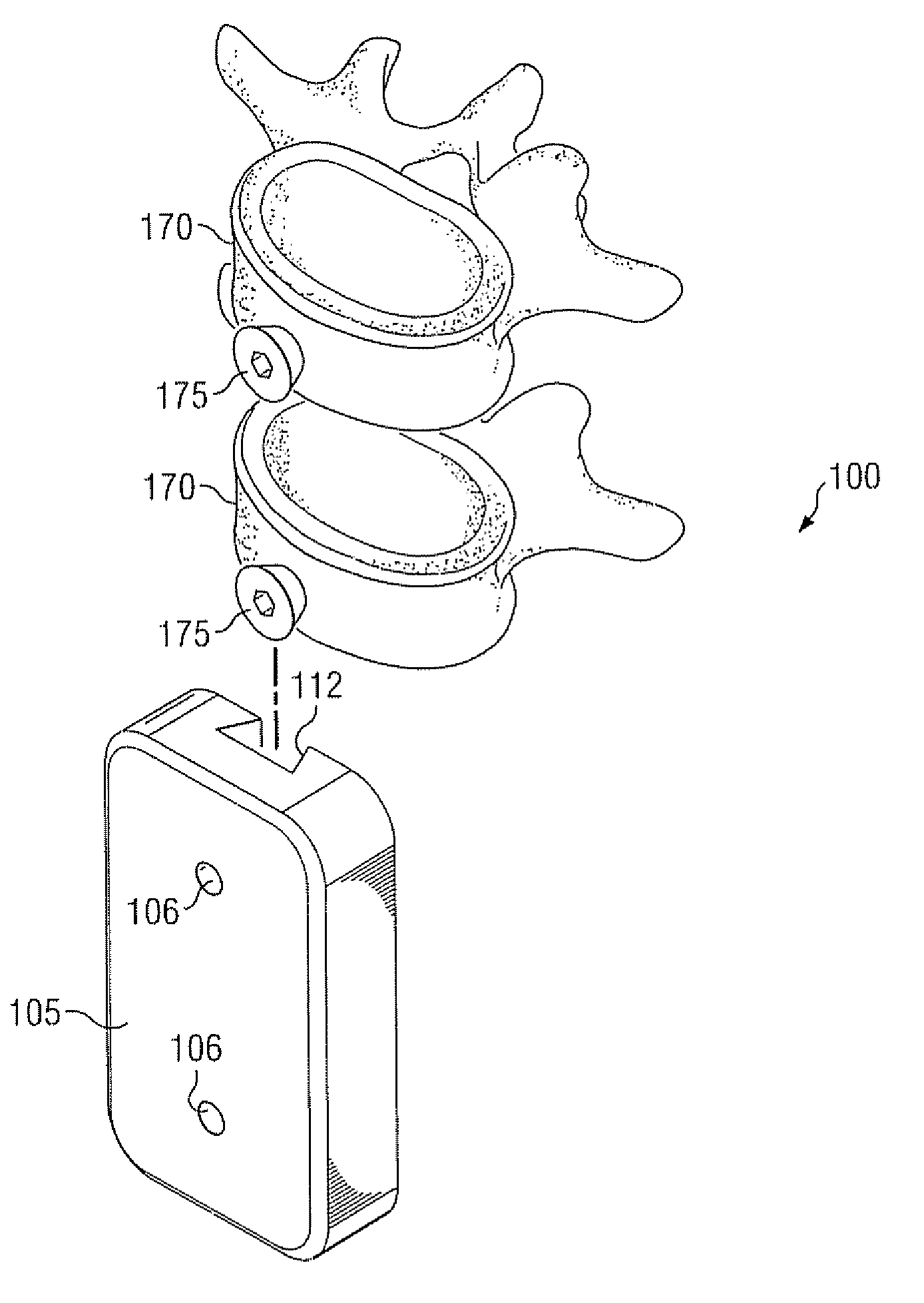
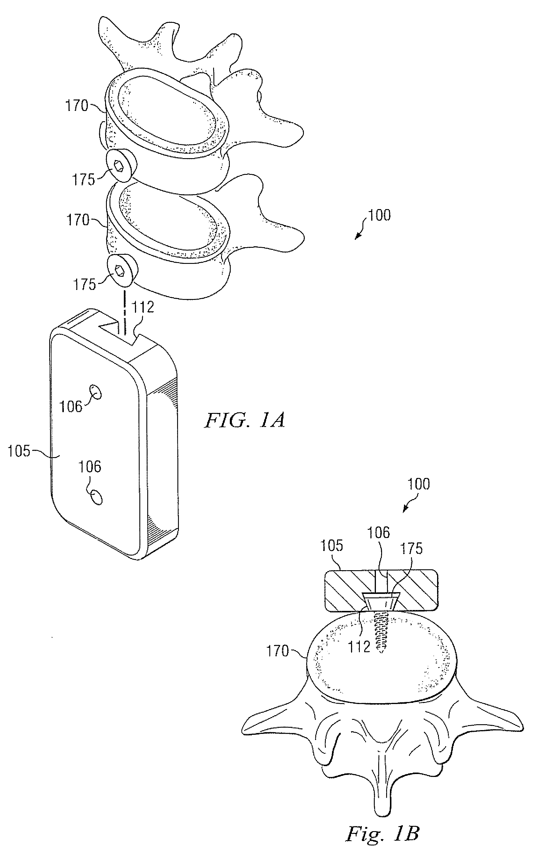
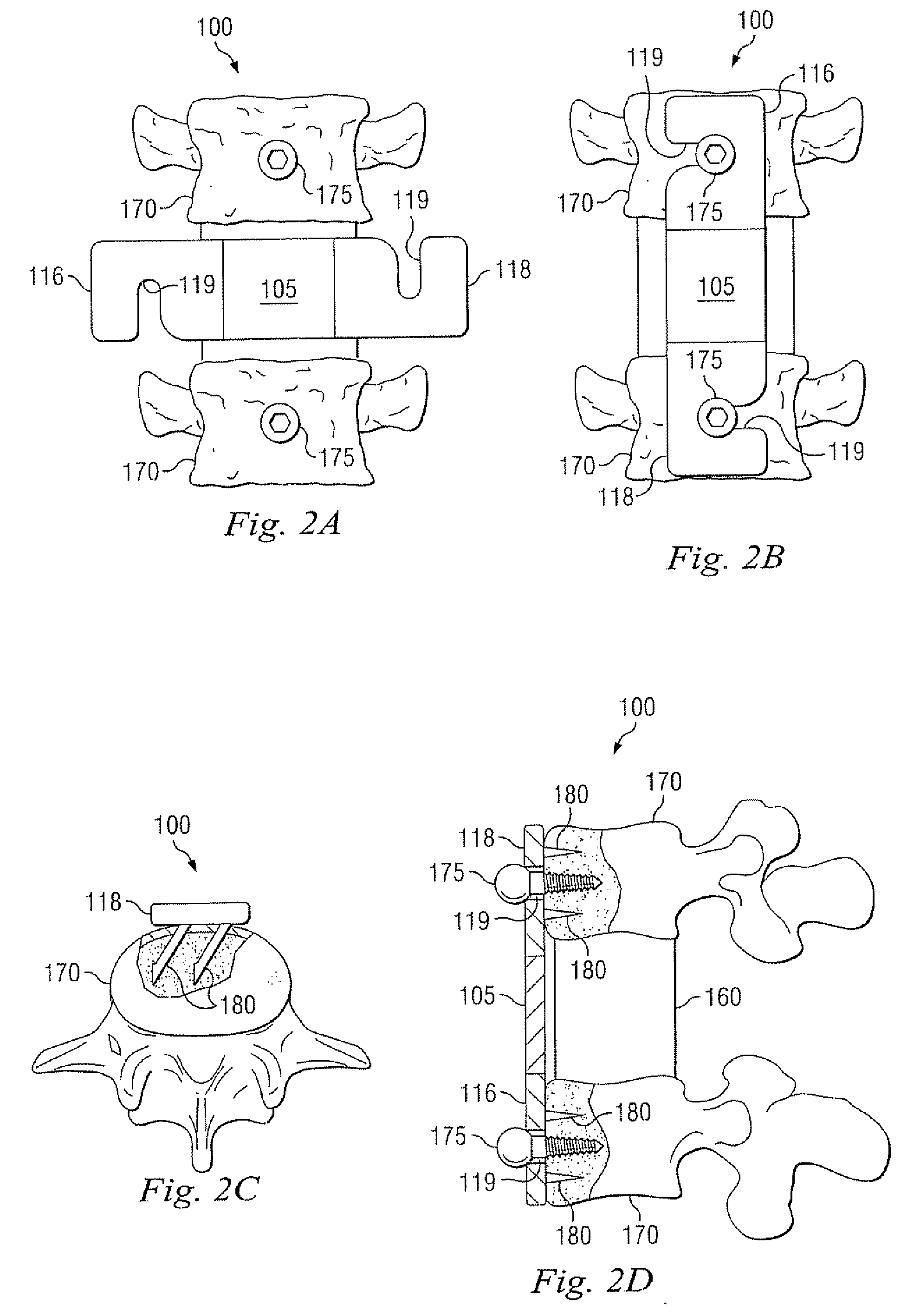
[0008]Embodiments of the present disclosure provide devices, systems and methods for stabilizing movement between bony tissues in a body, using fewer anchors, preventing screws from backing out, and causing less damage and stress to the body. One embodiment includes a plate assembly that allows medical professionals to implant anchors into the bony tissue and then attach the plate assembly to the anchors. In this embodiment, a plate assembly is configured to capture a portion of a first anchor on a first bony tissue and a portion of a second anchor located in a second bony tissue, and is further configured to prevent the first anchor from backing out of the first bony tissue and the second anchor from backing out of the second bony tissue. In some embodiments, the plate assembly is configured with an attachment feature such as a track. In some embodiments the plate has a first end with a recessed portion on a first edge shaped to receive the portion of the first anchor and a second end with a recessed portion on a second edge obverse from the first edge shaped to receive the portion of the second anchor, and

Problems solved by technology

However, these methods and systems are undesirable because of the obstacles to overcome when implanting the plate and the subsequent risk that screws holding the plate in place will back out.
A disadvantage with implanting prior art systems involves lining up the plate with the vertebral bodies.
This can make it difficult to ensure that the plate is aligned to the satisfaction of the surgeon.
Somewhat related to the problem of alignment is the difficulty of anchoring the plate in place.
The difficulty of anchoring the plate may be the result of at least two related problems: the use of multiple screws and positioning of the screws.
However, multiple screws may be undesirable or even contraindicated in certain situations.
Positioning the screws is difficult due to the lateral approach cited above, as well as the need for extensive retracti

Method used


Image

  • Device and system for stabilizing movement between bony tissue and method for implanting
  • Device and system for stabilizing movement between bony tissue and method for implanting
  • Device and system for stabilizing movement between bony tissue and method for implanting

Examples


Embodiment Construction

[0026]The disclosure and the various features and advantageous details thereof are explained more fully with reference to the non-limiting embodiments that are illustrated in the accompanying drawings and detailed in the following description. Descriptions of well known starting materials, processing techniques, components and equipment are omitted so as not to unnecessarily obscure the disclosure in detail. Skilled artisans should understand, however, that the detailed description and the specific examples, while disclosing preferred embodiments of the disclosure, are given by way of illustration only and not by way of limitation. Various substitutions, modifications, additions or rearrangements within the scope of the underlying inventive concept(s) will become apparent to those skilled in the art after reading this disclosure.

[0027]Reference is now made in detail to the exemplary embodiments of the disclosure, examples of which are illustrated in the accompanying drawings. Wherev...


PUM


Abstract

A device and system for stabilizing movement between two or more vertebral bodies and methods for implanting. Specifically, embodiments of the present disclosure may provide medical professionals the ability to selectively position and orient anchors in bony tissue and then attach a plate to the pre-positioned anchors. The plate assembly, once positioned on the anchors, prevents the anchors from backing out of the bony tissue.

Description

TECHNICAL FIELD OF THE DISCLOSURE[0001]This disclosure relates generally to stabilizing movement between bony tissues within a body, and in particular to systems and methods for stabilizing movement between vertebral bodies. Even more particularly, embodiments of the present disclosure relate to systems and methods for stabilizing movement between vertebral bodies in the cervical portion of the spine.BACKGROUND OF THE DISCLOSURE[0002]In medical situations, it is sometimes necessary to limit or eliminate movement between bony tissues such as vertebral bodies, either temporarily or permanently. As an example, after an accident, it may be necessary to temporarily limit the movement of vertebrae to prevent possible damage to the spinal cord that could lead to paralysis. As another example, during treatment for a degenerative disk, permanent fusion of two or more adjacent vertebral bodies may be necessary to alleviate pain or preserve some functionality.[0003]Prior art systems generally ...

Claims


Application Information

Patent Timeline
IPC IPC(8): A61B17/70A61B17/58A61B17/56A61B17/04A61F2/44
CPCA61B17/7007A61B17/7059A61F2/44A61F2002/30471A61F2002/3054A61F2002/30578A61F2220/0091
Inventor BERGERON, BRIAN J.FORTON, CHARLES R.LEMOINE, JEREMY J.MURDOCK, JAMIE R.
Owner ZIMMER SPINE INC
Why Eureka
Try Eureka