

Imaging of Formation Structure Ahead of the Drill-Bit
a formation structure and drill bit technology, applied in the field of acoustic logging while drilling equipment, can solve the problems of stalling the completion of the well, affecting the drilling work already done, and not being completely reliable in seismic information at great depths
- Summary
- Abstract
- Description
- Claims
- Application Information
AI Technical Summary
Benefits of technology
Problems solved by technology
Method used
Image

Examples
Embodiment Construction
[0026]In view of the above, the present disclosure through one or more of its various aspects and / or embodiments is presented to provide one or more advantages, such as those noted below.
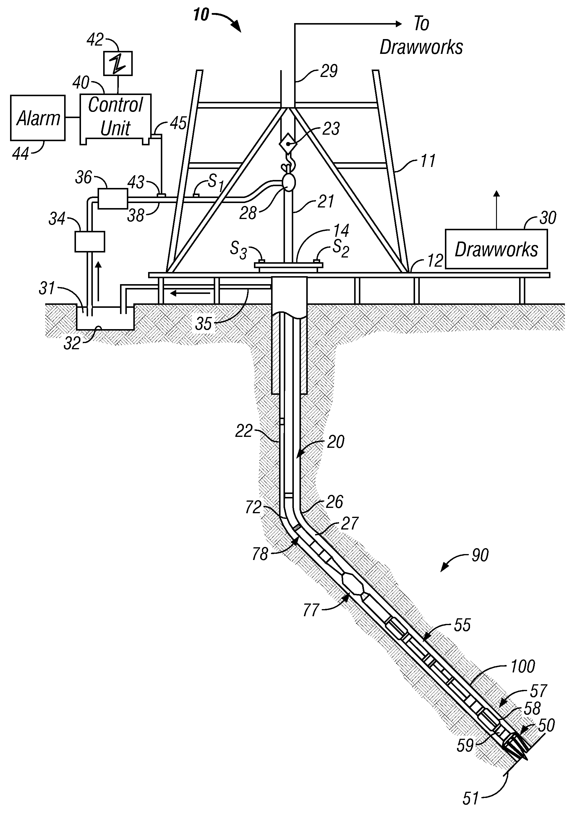
[0027]FIG. 1 illustrates a schematic diagram of an MWD drilling system 10 with a drill string 20 carrying a drilling assembly 90 (also referred to as the bottom hole assembly, or “BHA”) conveyed in a “wellbore” or “borehole”26 for drilling the wellbore. The drilling system 10 includes a conventional derrick 11 erected on a floor 12 which supports a rotary table 14 that is rotated by a prime mover such as an electric motor (not shown) at a desired rotational speed. The drill string 20 includes tubing such as a drill pipe 22 or a coiled-tubing extending downward from the surface into the borehole 26. The drill string 20 is pushed into the wellbore 26 when a drill pipe 22 is used as the tubing. For coiled-tubing applications, a tubing injector (not shown), however, is used to move the tubing from a sou...
PUM
 Abstract
Description
Claims
Application Information