Systems, methods, and devices for managing emergency power supply systems

a power supply system and emergency technology, applied in the field of industrial automation systems, can solve the problems of loss of utility power, inconvenience of power loss, power loss during medical operations, etc., and achieve the effect of facilitating the transfer of electrical power

Active Publication Date: 2008-12-18
GENERAC POWER SYSTEMS
View PDF34 Cites 105 Cited by
  • Summary
  • Abstract
  • Description
  • Claims
  • Application Information

AI Technical Summary

Benefits of technology

[0033]According to another embodiment, a method is described herein for testing emergency power supply system (EPSS) equipment at a facility. Generally, the EPSS equipment includes at least one automatic transfer switch (ATS), and the EPSS equipment is operatively connected to an EPSS management computer system for managing the EPSS equipment. In one aspect, the EPSS management computer system receives a test initiation command for initiation of a test of one or more items of EPSS equipment. In one aspect, the test initiation command is generated by a user via a graphical user interface (GUI), and the test initiation command includes one or more testing parameters. Upon receipt of the test initiation command, the EPSS management computer system creates a data record for each of the items of EPSS equipment that are subje

Problems solved by technology

Loss of utility power may be due to any number of causes, such as downed power lines, planned blackouts, malfunctions at a sub-station, inclement weather, and the like.
For some facilities, loss of power is merely an inconvenience.
Also, a loss of power during a medical operation would likely have severe results, including potential death of the patient.
Obviously, managing such a vast amount of equipment spread across acres or even miles of a facility is a tremendous challenge.
However, humans can often make mistakes, and fail to notice vital problems with the EPSS equipment.
Or, the equipment may break or experience a malfunction between checks, during which time a power loss may occur.
Further, given the vast size of many facilities, sheer limitations on experienced personnel may prevent a facility from adequately managing its vital EPSS equipment.
Because this testing is done by hand, it is inefficient, inaccurate, and cumbersome, and often some tests are overlooked or simply ignored.
Further, during a power outage or crisis event, there is traditionally no way to actively monitor the status of running or standby EPSS equipment without physically going to the equipment and checking on

Method used


Image

  • Systems, methods, and devices for managing emergency power supply systems
  • Systems, methods, and devices for managing emergency power supply systems
  • Systems, methods, and devices for managing emergency power supply systems

Examples


first embodiments

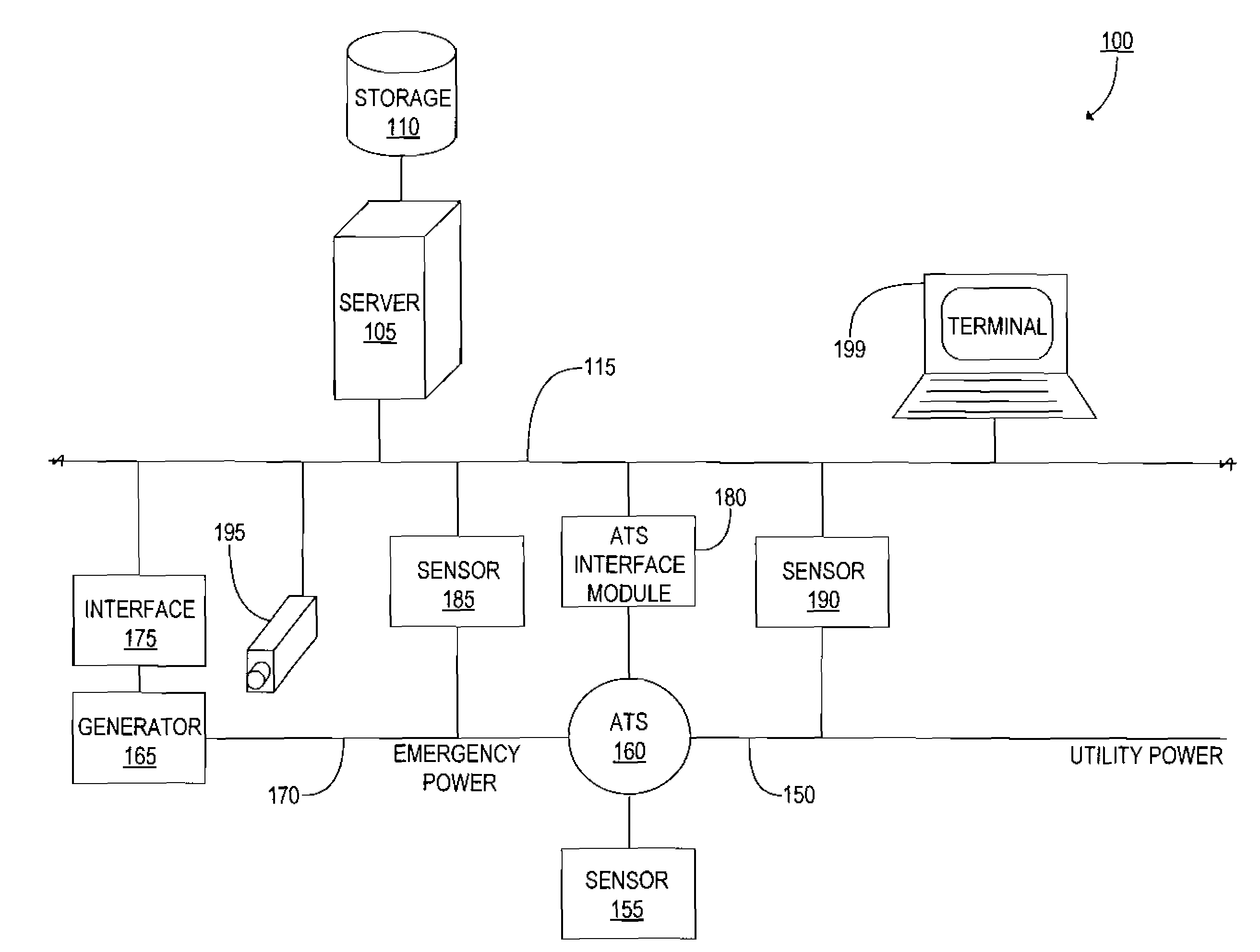
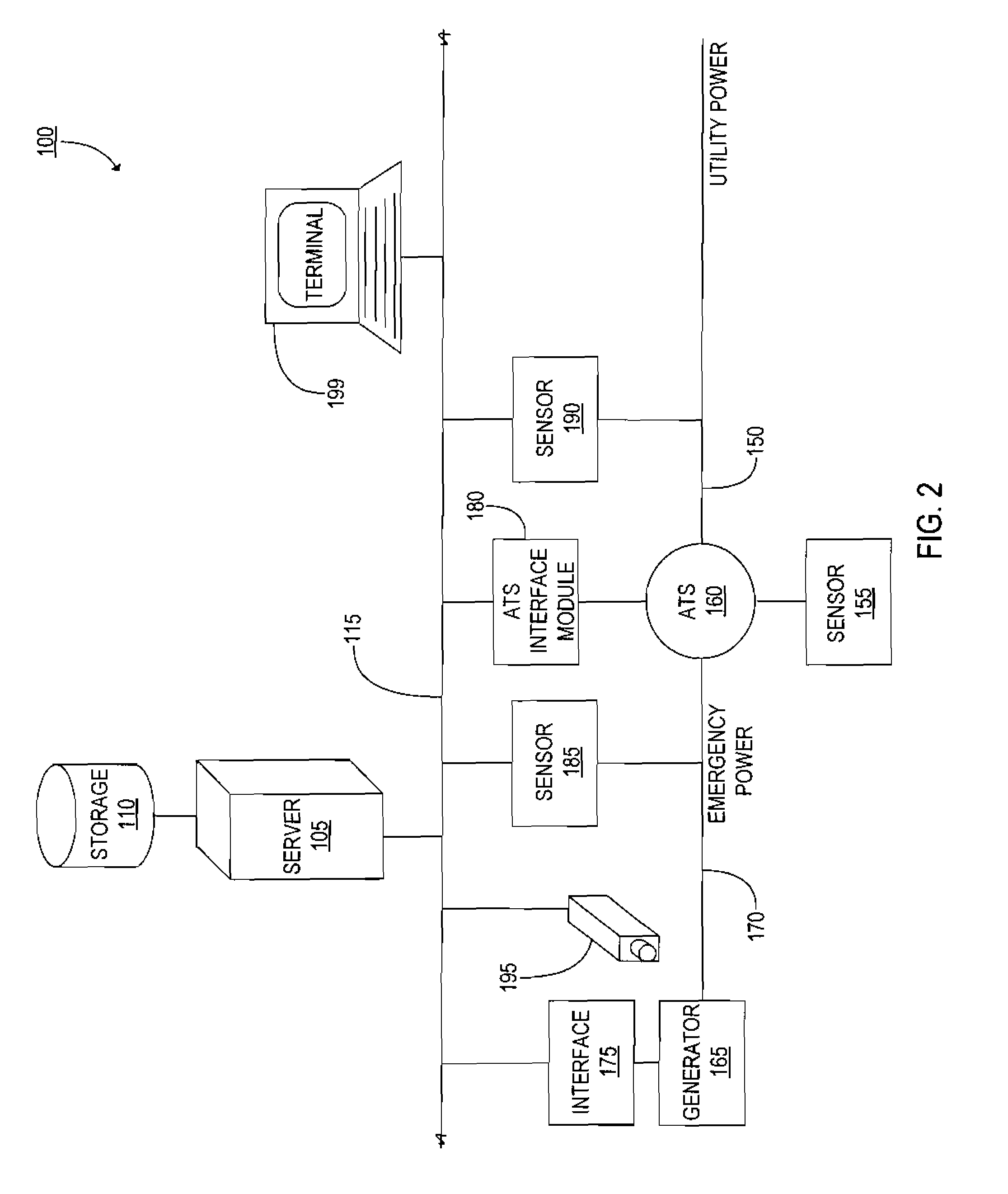
[0142]Generally, one form of the present disclosure is a system for monitoring, managing, and testing a power system having local generators and connections to the utility power grid. Turning to FIG. 2, a system 100 is shown with a server 105 and storage 110 connected to data network 115. Server 105 in this embodiment includes processor 120, memory 125, network interface 130, input interface 135, and output interface 140, as shown in FIG. 3 and as will be understood by those skilled in the art. Power, ground, clock, and other signals and circuitry are omitted for clarity, but will be understood and easily implemented by those skilled in the art.

[0143]With continuing reference to FIG. 3, network interface 130 in this embodiment connects server 105 to network 115 for communication of data between server 105 and other devices attached to network 115. Input interface 135 manages communication between processor 120 and one or more push-buttons, UARTs, IR and / or RF receivers or transceive...


PUM


Abstract

Aspects of the present disclosure generally relate to systems and methods for managing and monitoring a plurality of emergency power supply systems (EPSS's) at a facility via an emergency power management system (EPMS). The EPMS generally comprises EPSS equipment, a management computer system for managing, monitoring, and testing the operational characteristics of the EPSS equipment, and a plurality of interface modules for providing unified communication capabilities between the management computer system and the EPSS equipment. Additional aspects relate to methods for easily and efficiently creating and installing an EPMS at a facility. Further aspects are directed to providing predictive analyses related to the EPSS equipment. Also, aspects of the present disclosure relate to normalizing EPSS equipment information across varying vendors, makes, and models of equipment so as to provide a unified view of all equipment across a given facility.

Description

CROSS REFERENCE TO RELATED APPLICATIONS[0001]This application is a continuation-in-part and claims benefit under 35 U.S.C. § 120 of U.S. patent application Ser. No. 11 / 556,496, filed Nov. 3, 2006, and entitled “Power Monitoring and Testing”, now U.S. Pat. No. ______, which claims benefit under 35 U.S.C. § 119(e) of U.S. Provisional Patent Application No. 60 / 823,474, filed Aug. 24, 2006, and entitled “Test and Monitoring System”, each of which are incorporated herein by reference in their entirety.TECHNICAL FIELD[0002]The present systems, methods, and devices relate generally to industrial automation systems, and more particularly to managing, monitoring, and testing emergency power supply systems.BACKGROUND[0003]Many facilities require backup power systems to generate power in case of emergencies or when conventional power systems fail. These backup power systems, commonly referred to as emergency power supply systems (EPSS's), provide power to a facility when utility power is unava...

Claims


Application Information

Patent Timeline
IPC IPC(8): G06Q10/00G06Q30/00G06F19/00G01R19/00G01R31/00G01R15/00G06F17/30
CPCG06Q10/063118G06Q10/06313G06Q10/06315G06Q10/06395G06Q30/0601H02J13/0079H04Q9/00G06F1/26G01F13/006G06F17/00G01R31/40G06F17/10Y04S10/30Y02E60/74H04Q2209/10H04Q2209/86Y04S50/10H02J13/00002H02J13/00017H02J13/00028H02J13/00034Y02E60/00Y04S40/124
Inventor WITTER, BRADLEY JAYBUTLER, THOMAS JOSEPHSCOUFIS, JOSEPH J.REICHEL, ERIC D.
Owner GENERAC POWER SYSTEMS
Why Eureka
Try Eureka