Aircraft combination engines thermal management system

US20080314573A1Inactive Publication Date: 2008-12-25RAYTHEON TECH CORP

Image

  • Aircraft combination engines thermal management system
  • Aircraft combination engines thermal management system
  • Aircraft combination engines thermal management system

Examples


Embodiment Construction

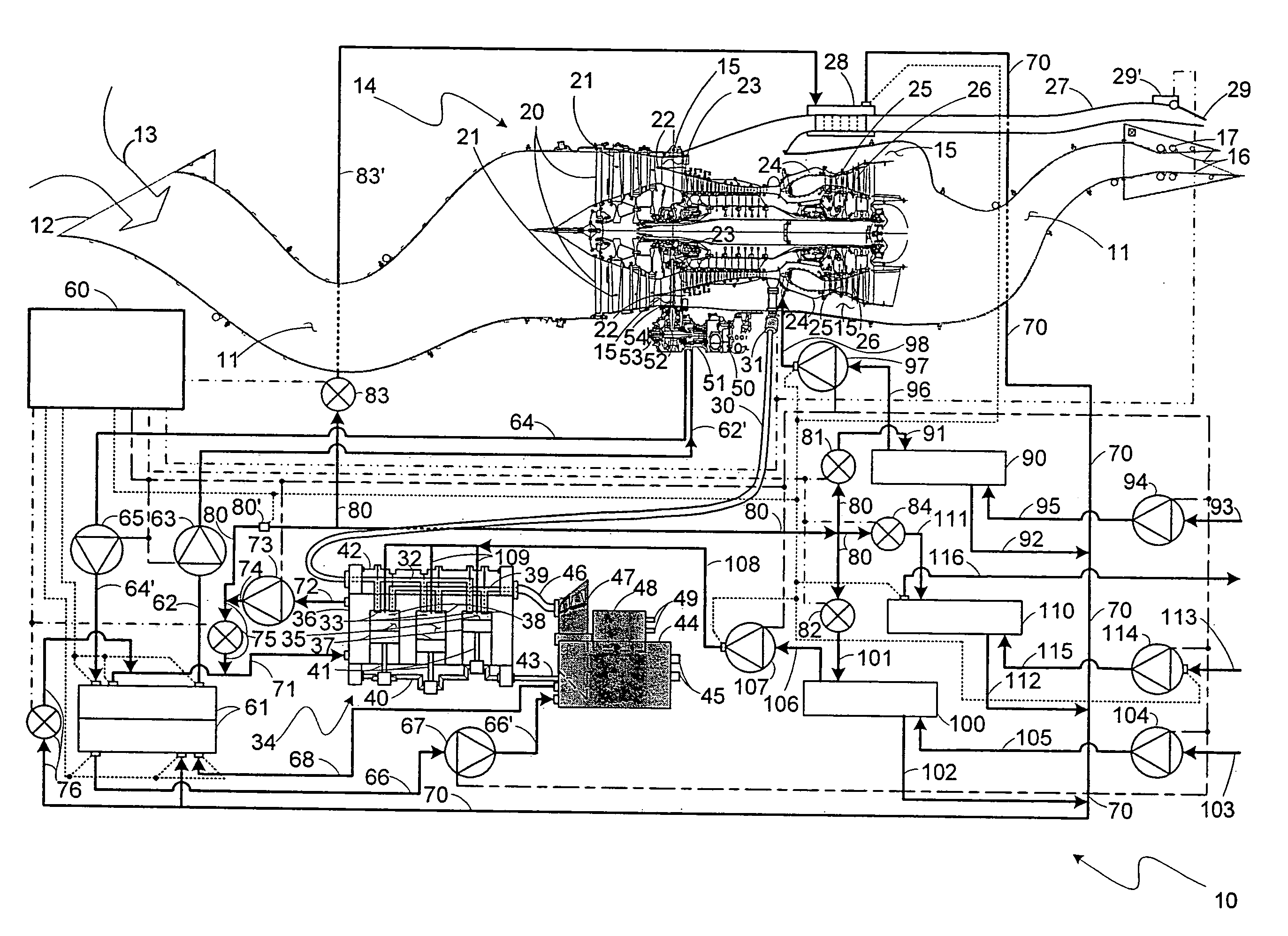
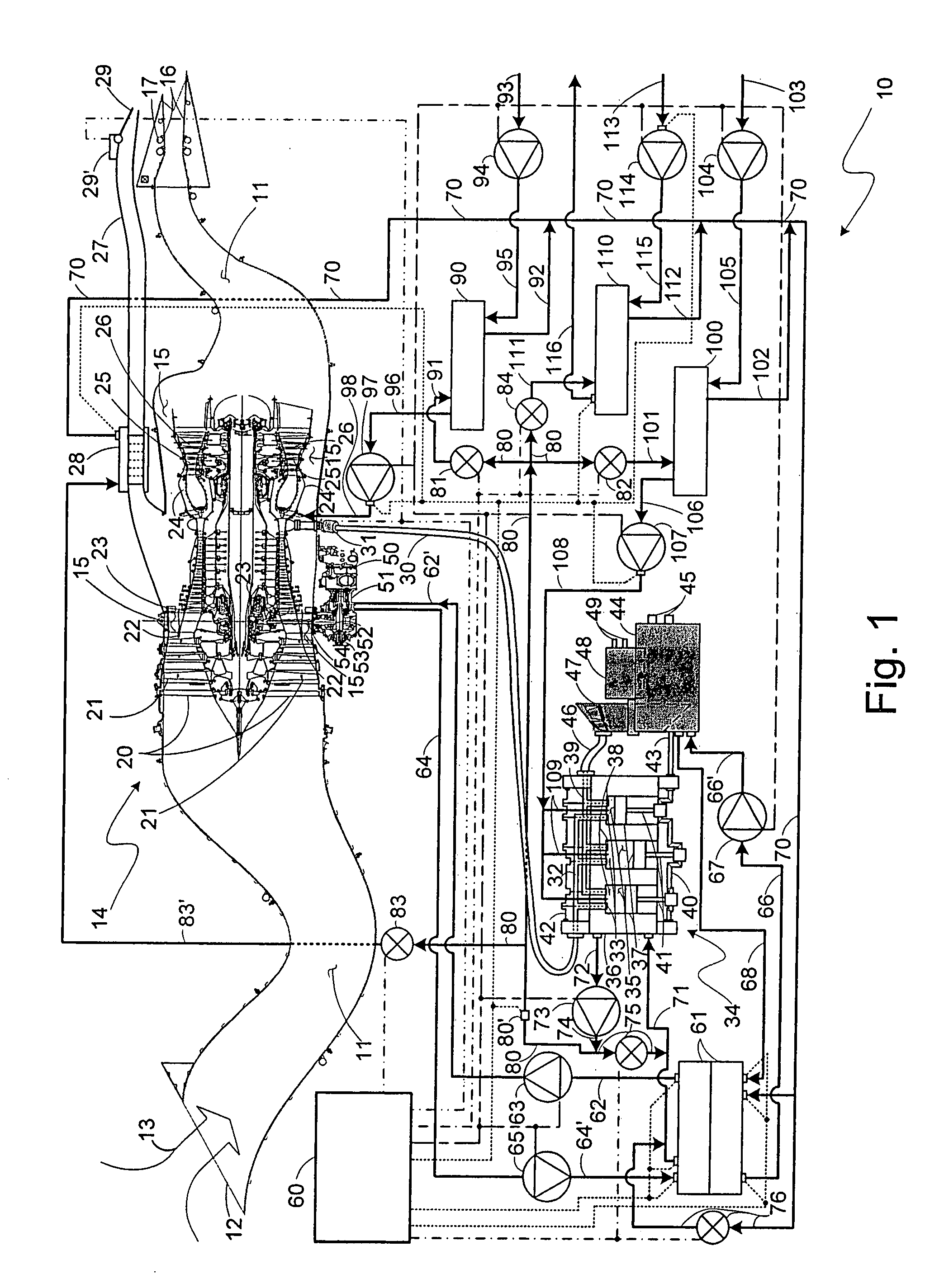
[0014]Keeping heat in operating internal combustion engines of all kinds that has been generated in those engines during such operation thereof increases the thermodynamic efficiency of those operations. Of course, there are limits to operating those engines with such a goal that are imposed by the maximum temperatures that various engine components can withstand before failing in some manner. These limits are avoided typically by providing suitable cooling arrangements of some sort for the engines, and sometimes their loads devices, but such cooling should not be overdone as this cooling requires using energy therefor that is typically supplied from the engines being cooled. Such energy use thereby reduces the energy from the engines that would otherwise be available for propulsion or such other tasks that have been assigned to the engine. That is, the engines and their loads should be operated at their maximum feasible operating temperatures for reasons of efficiency.

[0015]In an a...


PUM


Abstract

An engine combination for generating forces with a gas turbine engine generating force that utilizes an engine lubricant for lubricating moving components in the turbofan engine, and an internal combustion engine provided in the combination as an intermittent combustion engine generating force that utilizes a coolant for transporting heat generated in the intermittent combustion engine away therefrom and having an air intake, there being an air transfer duct connected from a compressor in the gas turbine engine to the air intake to transfer compressed air thereto. A coupling heat exchanger is coupled to both the gas turbine engine and the intermittent combustion engine to have the engine lubricant and the coolant pass therethrough to thereby permit the coolant to transport heat in the engine lubricant away therefrom. A further cooling heat exchanger is coupled to both the coupling heat exchanger and the intermittent combustion engine to have a remote fluid from a source thereof and the coolant pass therethrough to permit the remote fluid to transport heat in the coolant away therefrom, and with the coolant also circulating through at least one of the coupling heat exchanger and the intermittent combustion engine.

Description

CROSS-REFERENCE TO RELATED APPLICATION[0001]Referenced herein is U.S. application Ser. No. 11 / 713,262 filed Mar. 2, 2007 for “COMBINATION ENGINES FOR AIRCRAFT” by Frederick M. Schwarz, Brian M. Fentress, Andrew P. Berryann, Charles E. Lents and Jorn A. Glahn.BACKGROUND OF THE INVENTION[0002]The present invention relates to gas turbine engines for aircraft and, more particularly, to gas turbine engines each coupled to a corresponding auxiliary engine.[0003]Gas turbine engines as continuous combustion, open Brayton cycle internal combustion engines have come to dominate as the power plants for larger, faster aircraft to essentially the exclusion of reciprocating engines, or internal, intermittent combustion engines, earlier used as power plants for these kinds of aircraft. This is largely because of the greater power-to-weight ratio of gas turbine engines versus internal combustion engines, especially in large horsepower engines, or, more appropriately, large thrust engines in which t...

Claims


Application Information

Patent Timeline
25 Dec 2008
Publication
US20080314573A1
IPC
F28F3/02
CPC
F01D15/10; Y02T50/676; F01D13/02; F01D25/125; F02K3/06; F02K3/115; F02C6/08; F02C6/10
Inventors
SCHWARZ, FREDERICK M.; GLAHN, JORN A.