
Vehicle with Tilt Detection Based on Fuel Gauge Output

a technology of fuel gauge and tilt sensor, which is applied in the field of vehicles, can solve the problems of increasing the number of components, the inability of the tilt sensor to occupy the space in the vicinity, and the overall manufacturing cost of the vehicle, so as to achieve the effect of not increasing the components and the manufacturing cos

Inactive Publication Date: 2008-12-25
KAWASAKI HEAVY IND LTD
View PDF1 Cites 21 Cited by
  • Summary
  • Abstract
  • Description
  • Claims
  • Application Information

AI Technical Summary

Benefits of technology

[0004]The present invention addresses the above described conditions, and an object of the present invention is to provide a vehicle which is capable of detecting that a body of the vehicle is tilted by efficiently utilizing a body space of the vehicle without increasing components and a manufacturing cost.
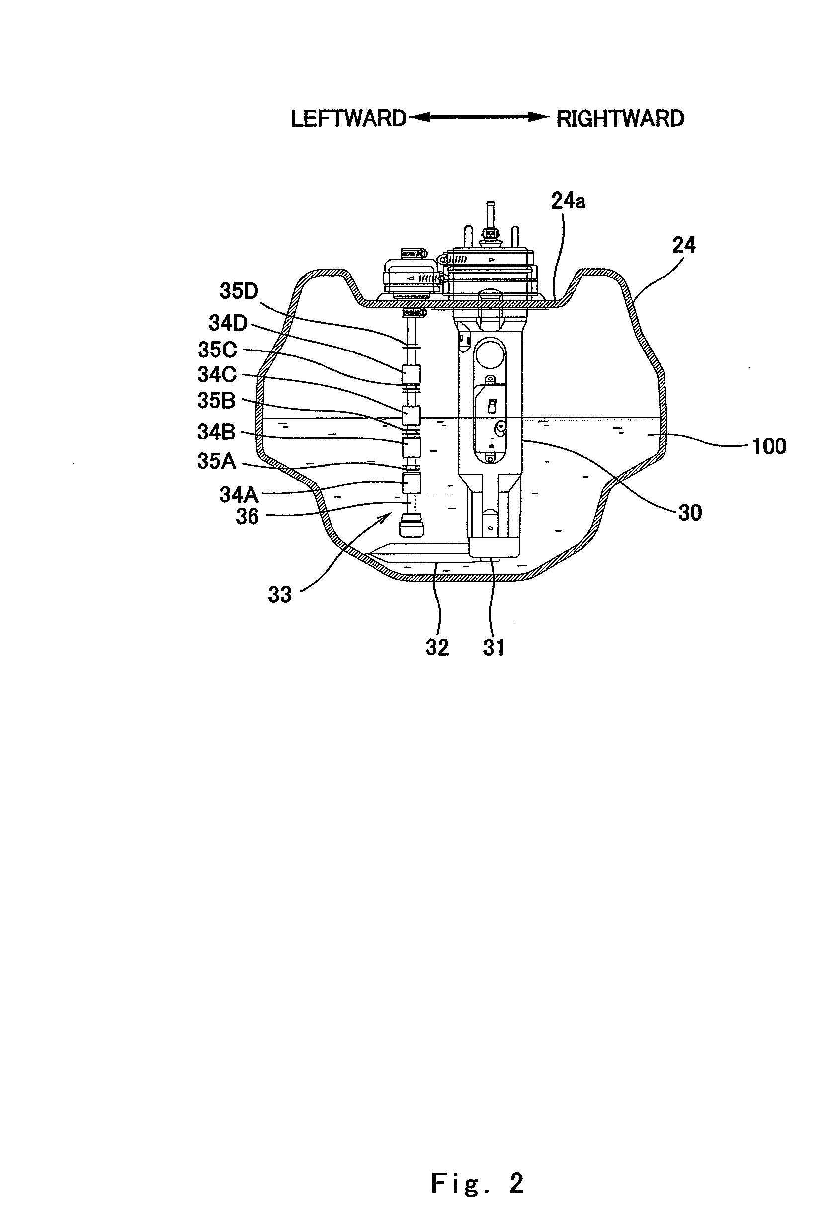
[0006]In such a configuration, when the body of the vehicle is tilted and the fuel tank changes its posture, the fuel gauge changes its posture and outputs a signal different from that in a normal state. By monitoring the signal output from the fuel gauge, it can be determined whether or not the body of the vehicle is tilted. So, a tilting sensor for exclusive use may be omitted. Therefore, the space which would be occupied by the tilting sensor can be efficiently used for other components. Furthermore, since brackets or electric wires for the tilting sensor are omitted, the number of components and manufacturing cost of the vehicle can be reduced.
[0016]In such a configuration, since the fuel gauge for displaying the fuel amount information in the fuel amount display device is used to detect whether or not the body of the vehicle is tilted, the number of components and manufacturing cost of the vehicle can be reduced.
[0020]In such a configuration, when the body of the vehicle is returned from the tilted state to the untilted state, the engine is allowed to start. This makes it possible to start driving in a short time after the body of the vehicle has been tilted.
[0022]In such a configuration, when the user returns the posture of the vehicle from the tilted state to the untilted state, the user has only to operate the start-up input device to start the engine without resetting the power supply switch. Therefore, it becomes possible to start driving in a short time after the body of the vehicle has been tilted. On the other hand, in the state where the body of the vehicle is tilted, the engine cannot be started unless the start-up input device is operated after the power supply switch is reset. This makes it possible to inhibit the engine from being started in the state where the body of the vehicle is tilted.

Problems solved by technology

For these reasons, it is undesirable for the tilting sensor to occupy the space in the vicinity of the center of gravity of the body.
In addition, brackets and electric wire are needed to mount the tilting sensor in the vehicle, increasing structural members, the number of components, and the overall manufacturing cost of the vehicle.

Method used


Image

  • Vehicle with Tilt Detection Based on Fuel Gauge Output
  • Vehicle with Tilt Detection Based on Fuel Gauge Output
  • Vehicle with Tilt Detection Based on Fuel Gauge Output

Examples


embodiment 1

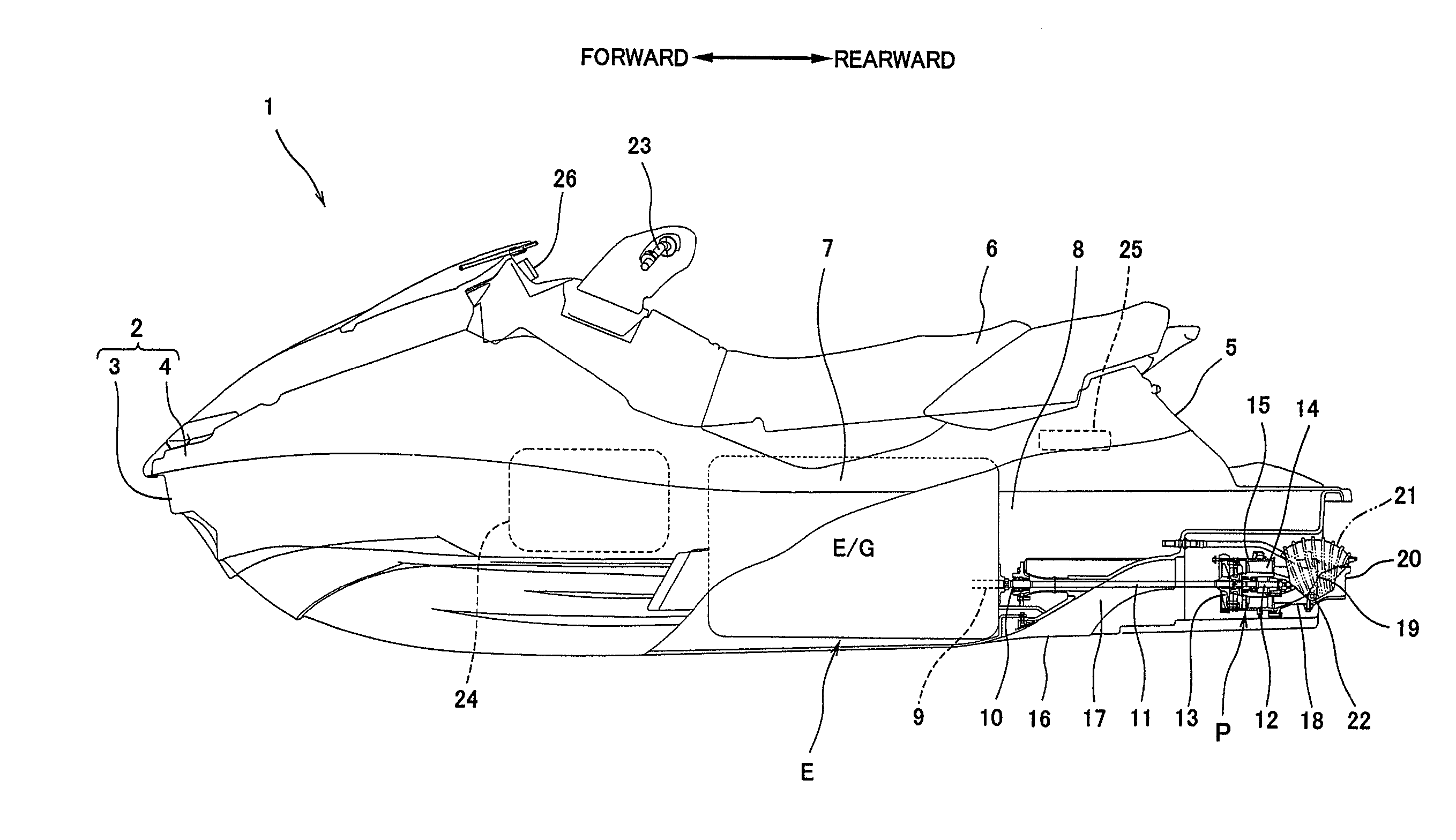
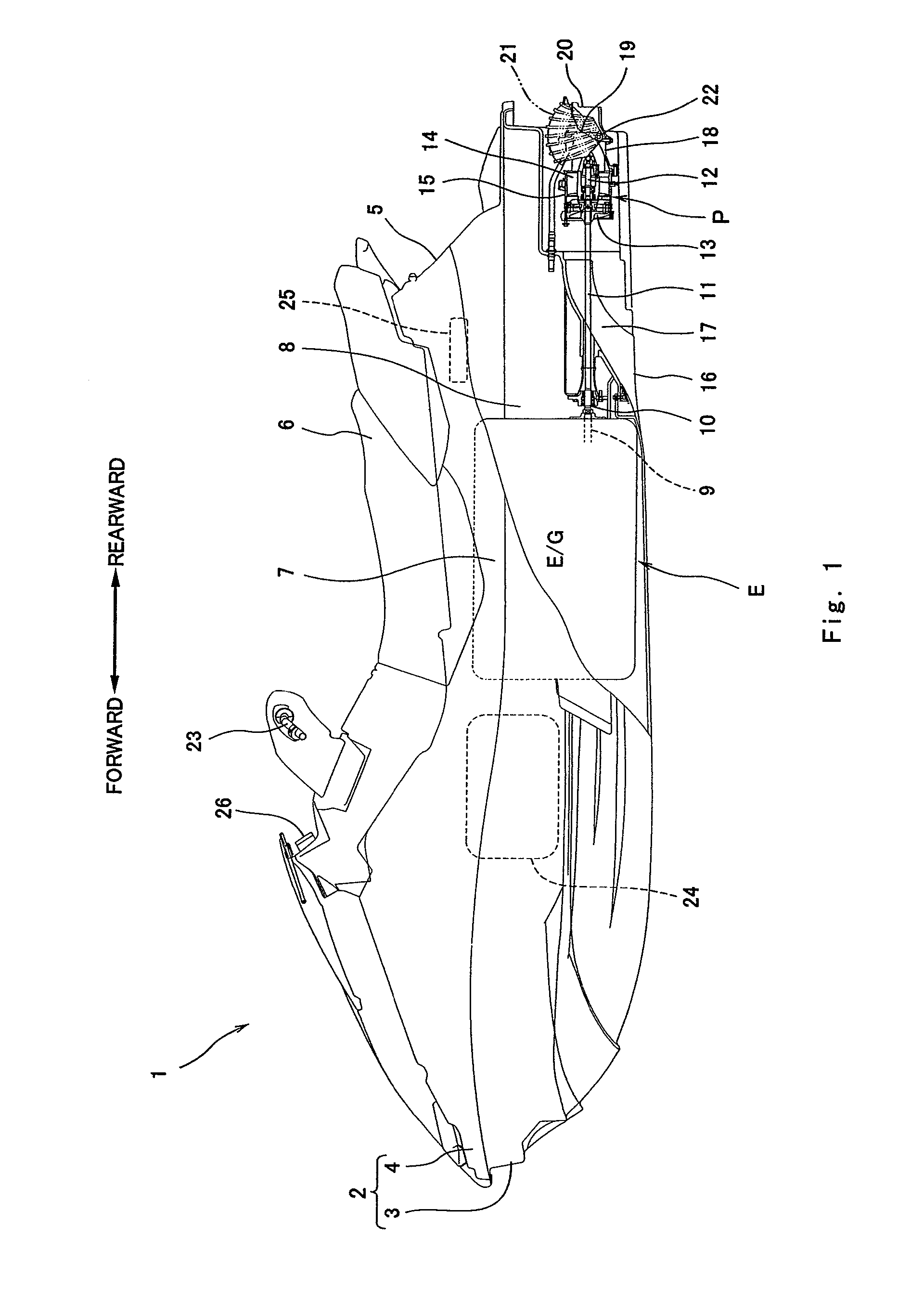
[0042]FIG. 1 is a left side view of a jet-propulsion personal watercraft 1 according to a first embodiment of the present invention. With reference to FIG. 1, the jet-propulsion personal watercraft 1 is a straddle-type jet-propulsion personal watercraft which is provided with a seat 6 straddled by a user. A body 2 of the watercraft 1 comprises a hull 3 and a deck 4 covering the hull 3 from above. A center portion (protruding portion) 5 in a width direction of a rear part of the deck 4 protrudes upward. The seat 6 is mounted over an upper surface of the protruding portion 5. A deck floor 7 is formed on right and left sides in the width direction of the protruding portion 5 to be substantially flat and lower than the protruding portion 5 to enable user's feet to be put thereon.

[0043]In an inner space 8 defined by the hull 3 and the deck 4 below the seat 6, an engine E is disposed in a center of gravity of the body 2. The engine E is mounted in the engine room 8 in such a manner that a...

embodiment 2

[0069]FIG. 11 is a cross-sectional view of a fuel tank 124 in a jet-propulsion personal watercraft according to a second embodiment of the present invention, which corresponds to FIG. 2. As shown in FIG. 11, a fuel pump 130 is attached to an upper wall portion 124a of the fuel tank 124. The fuel pump 130 extends downward inside the fuel tank 124. A suction port 131 is provided at a lower end portion of the fuel pump 130. A mesh-shaped filter 132 is attached to protrude from the suction port 131. The fuel pump 130 is attached with a fuel gauge 133. The fuel gauge 133 includes a pivot lever 136 which is oriented in the lateral direction of the watercraft 1 with one end portion thereof coupled to the fuel pump 130, a float 134 attached to an opposite end portion of the pivot lever 136, and a lever angle detector 135 which is a variable resistor which detects an angle change in the pivot lever 136. When the fuel tank 124 is tilted clockwise or counterclockwise, the float 134 moves accor...


PUM


Abstract

A vehicle including an engine, a fuel tank configured to store a fuel supplied to the engine, a fuel gauge configured to detect a fuel level of the fuel inside the fuel tank, and a tilting detector configured to determine whether or not a body of the vehicle is tilted, based on a signal output from the fuel gauge.

Description

TECHNICAL FIELD[0001]The present invention relates to a vehicle which is capable of detecting tilting of the vehicle, such as a jet-propulsion personal watercraft (PWC), a three-wheeled or four-wheeled all terrain vehicle, or a motorcycle.BACKGROUND ART[0002]In conventional fuel injection systems (FI systems), a fuel injector injects a predetermined amount of fuel into an air-intake passage connected to an engine under control of an ECU (electronic control unit). In some vehicles including such FI systems, the ECU causes the fuel injector to stop fuel injection to forcibly stop running of the engine, when a tilting sensor detects that a body thereof is tilted a specified angle or larger.[0003]Typically, the tilting sensor is positioned in the vicinity of a center of gravity of the body to precisely detect that the body is tilted. In the vicinity of the center of gravity of the body, relatively bulky components such as the engine, a fuel tank, and an air cleaner box are disposed. If ...

Claims


Application Information

Patent Timeline
IPC IPC(8): B60K28/14B60K15/035B60W40/10B62J35/00B62J99/00B63B11/04B63B35/73F02D17/00F02D17/04F02D45/00G01F23/36G01F23/60
CPCB60Y2200/20B60Y2200/24B60Y2200/42B62J27/00B63B35/731B63B39/14B63B43/00G01F23/0076G01F23/36B60K15/00B60K28/14B60K2015/0319B60K2015/0772B60Y2200/12B63B34/10G01F23/804
Inventor KAMIO, KUNIHIKO
Owner KAWASAKI HEAVY IND LTD
Learn More