Damper having a rebound bumper and damper subassembly having same

a technology of damper and bumper, which is applied in the direction of shock absorbers, vibration dampers, springs/dampers, etc., can solve the problems of increasing damper rebound and damage to the suspension system

Inactive Publication Date: 2008-12-25
BWI CO LTD SA +1
View PDF10 Cites 4 Cited by
  • Summary
  • Abstract
  • Description
  • Claims
  • Application Information

AI Technical Summary

Benefits of technology

[0005]What is needed is an improved damper having a rebound bumper and an improved damper subassembly having a rebound bumper.

Problems solved by technology

Destruction or compression set of the rebound bumper results in an increase in damper rebound length beyond the design length which can damage the suspension system of vehicle employing the damper as a suspension damper.

Method used


Image

  • Damper having a rebound bumper and damper subassembly having same
  • Damper having a rebound bumper and damper subassembly having same
  • Damper having a rebound bumper and damper subassembly having same

Examples


Embodiment Construction

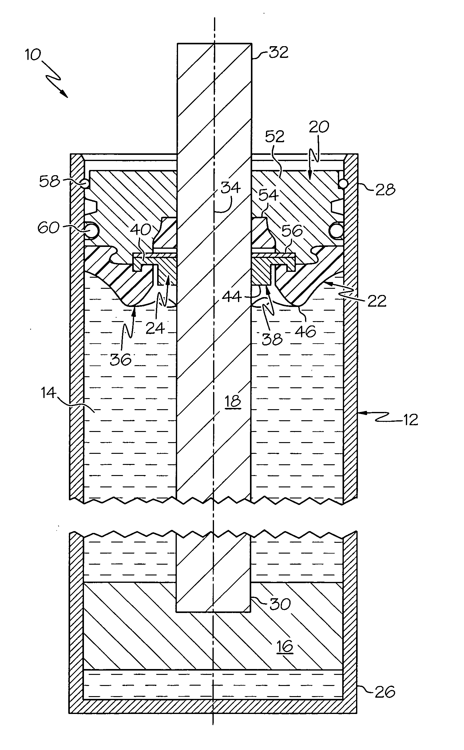
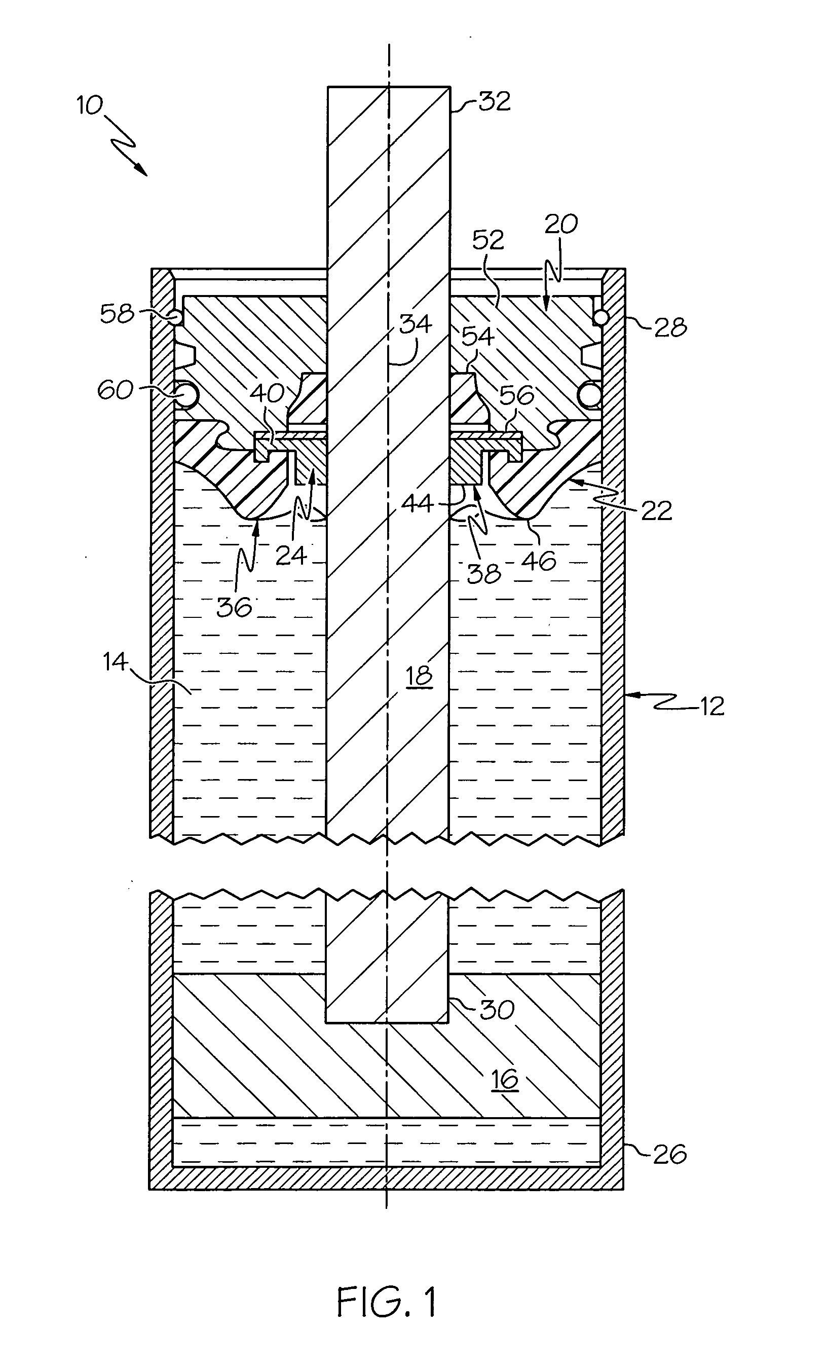
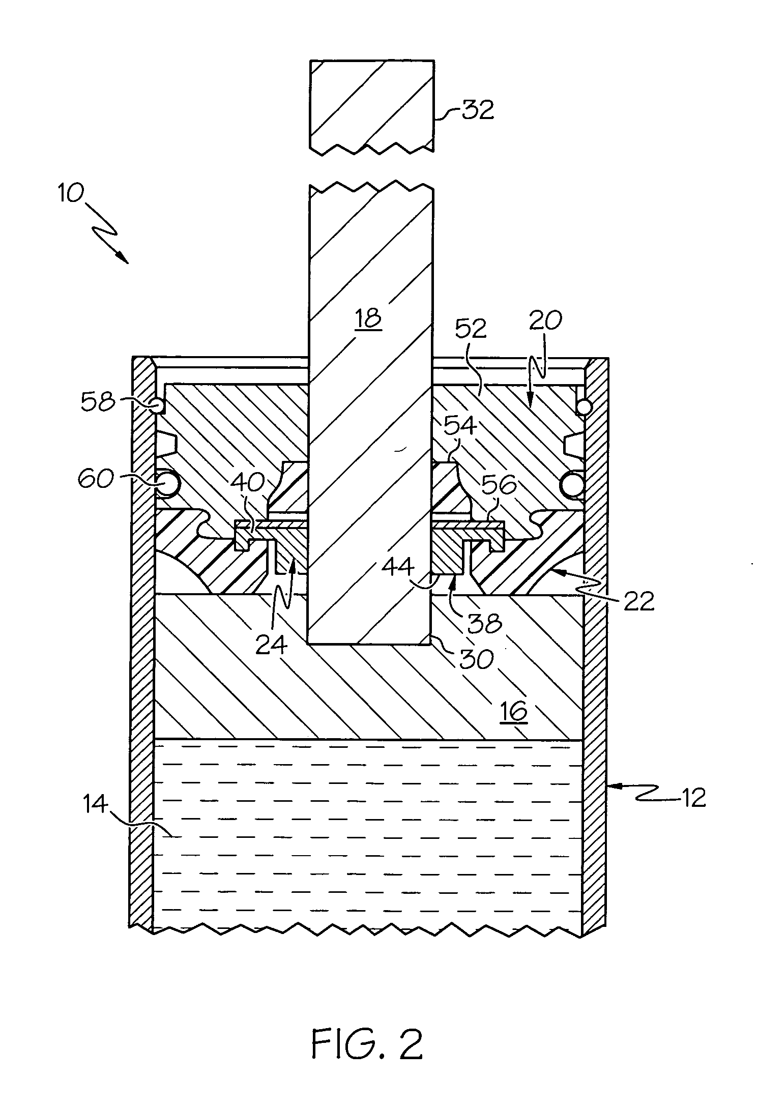
[0016]Referring now to the drawings, FIGS. 1-6 show an embodiment of the present invention. A first expression of the embodiment of FIGS. 1-6 is for a damper 10 including a damper cylinder 12, damping fluid 14, a damper piston 16, a piston rod 18, a rod guide assembly 20 (also known as a seal cover assembly), a compressible rebound bumper 22, and a rebound travel limiter 24. The damper cylinder 12 has a (monolithic or non-monolithic) closed end portion 26 and an open end portion 28. The damping fluid 14 is disposed within the damper cylinder 12. The damper piston 16 is disposed within, and slidingly engagable with, the damper cylinder 12. The piston rod 18 has a first end portion 30 attached to the damper piston 16 and a second end portion 32 extending outside the open end portion 28 of the damper cylinder 12. The rod guide assembly 20 is attached to the open end portion 28 of the damper cylinder 12 and is adapted to guide the piston rod 18 and to seal the damping fluid 14 within th...


PUM


Abstract

A damper includes a rod guide assembly which is attached to an open end portion of a cylinder. The rod guide assembly is adapted to guide a piston rod and to seal damping fluid within the cylinder. The damper includes a compressible rebound bumper disposed between, and attached to one of, the rod guide assembly and a piston. The damper includes a rebound travel limiter. In a first expression, the limiter is adapted to limit the compression of the bumper when the limiter is in contact with the rod guide assembly and the piston. In a second expression, the limiter is in contact with the bumper and the one of the rod guide assembly and the piston, wherein the limiter has a modulus of elasticity which is greater than that of the bumper. A damper subassembly is described which includes a compressible rebound bumper and a rebound travel limiter.

Description

CROSS REFERENCE TO RELATED APPLICATIONS[0001]The present application claims priority of U.S. Provisional Application No. 60 / 936,549 filed Jun. 20, 2007.TECHNICAL FIELD[0002]The present invention relates generally to piston dampers, and more particularly to a damper having a rebound bumper and to a damper subassembly having a rebound bumper.BACKGROUND OF THE INVENTION[0003]Conventional piston dampers include dampers having a tube and a piston assembly. The tube contains a damping fluid. The piston assembly includes a piston and a piston rod. The piston slideably engages the tube between the closed and open end portions of the tube. The piston rod has a first end portion attached to the damper piston and a second end portion extending outside the open end portion of the tube. A rod guide assembly is attached to the open end portion of the tube to guide the piston rod and to seal the damping fluid within the tube. A rebound bumper is attached (by a snap fit) to the piston-facing end po...

Claims


Application Information

Patent Timeline
Patent Type & Authority Applications(United States)
IPC IPC(8): F16F9/24
CPCF16F9/585
Inventor LUN, SAIMAN
Owner BWI CO LTD SA
Why Eureka
Try Eureka