

Video-Rate Holographic Surveillance System
a holographic surveillance and video rate technology, applied in the field of video rate holographic surveillance system, can solve the problems of limited application of holography to the problem of personnel surveillance, limitations and adverse effects of detection of concealed targets, and traditional inspection systems such as x-ray imaging systems, which are capable of near real-time detection and other problems, to achieve the effect of reducing the cost of holographic surveillan
- Summary
- Abstract
- Description
- Claims
- Application Information
AI Technical Summary
Benefits of technology
Problems solved by technology
Method used
Image

Examples
first embodiment
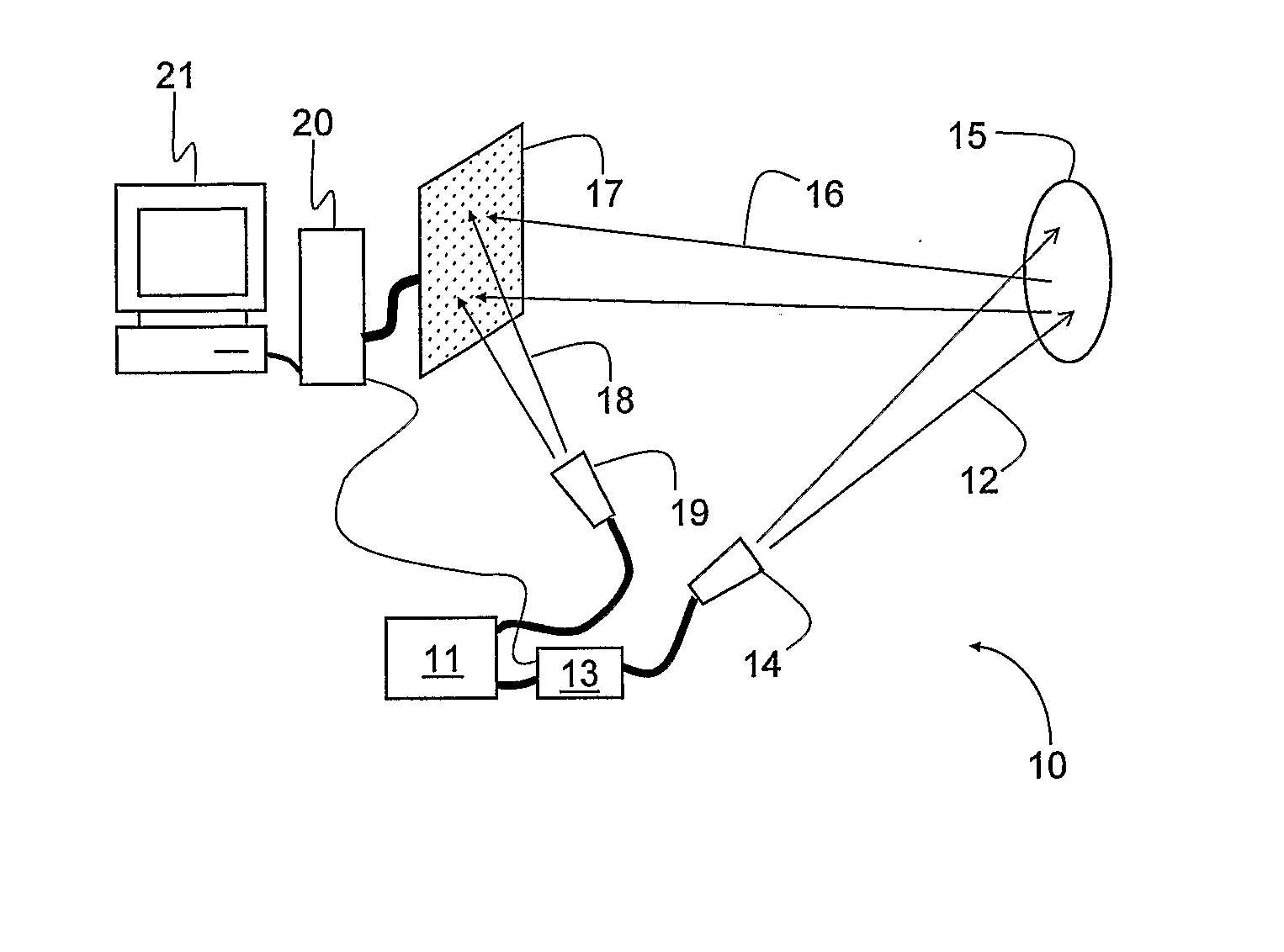
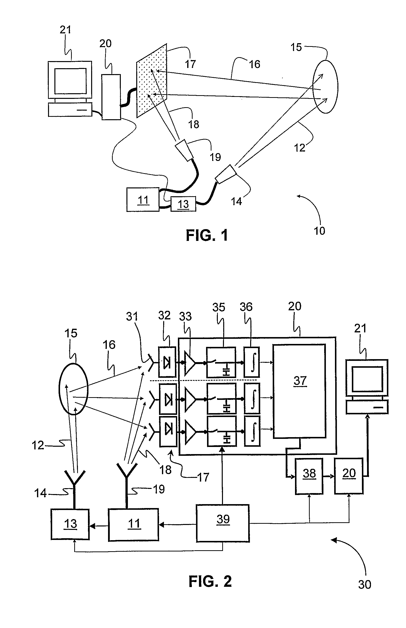
[0027]FIG. 1 shows schematically a holographic surveillance system 10 according to the invention comprising a microwave generator 11 that emits an incident beam 12 which is modulated by a modulator 13. A transmit antenna 14 coupled to the modulator 13 transmits the modulated incident beam 12 towards a target 15. The incident beam 12 is reflected by the target 15 to form a reflected beam 16, which strikes a receiver array 17. At the same time, a reference beam 18 is emitted by an antenna 19 towards the receiver array 17 so that two signals impinge on the receiver array 17, namely the reflected beam 16 and the reference beam 18. The signals impinging on the receiver array 17 are processed by a processor 20 and displayed on a display device of a computer 21, which also controls the microwave generator 11.
second embodiment
[0028]FIG. 2 shows schematically a holographic surveillance system 30 according to the invention, wherein components having similar functionality to those shown in FIG. 1 are referenced by identical reference numerals. A microwave generator 11 emits an incident beam 12 which is modulated by a modulator 13 and transmitted by a transmit antenna 14 towards a target 15. The incident beam 12 is reflected by the target 15 to form a reflected beam 16, which is propagated toward an array of receiving antennas 31 each coupled to a respective diode 32 of a diode array which together with the receiving antennas 31 constitutes a receiver array 17. At the same time, a reference beam 18 is emitted by an antenna 19 towards the receiver array 17 so that two signals impinge on the receiver array 17, namely the reflected beam 16 and the reference beam 18. The signals impinging on the receiver array 17 are processed by a processor 20 and displayed by a computer 21, which also controls the microwave ge...
third embodiment
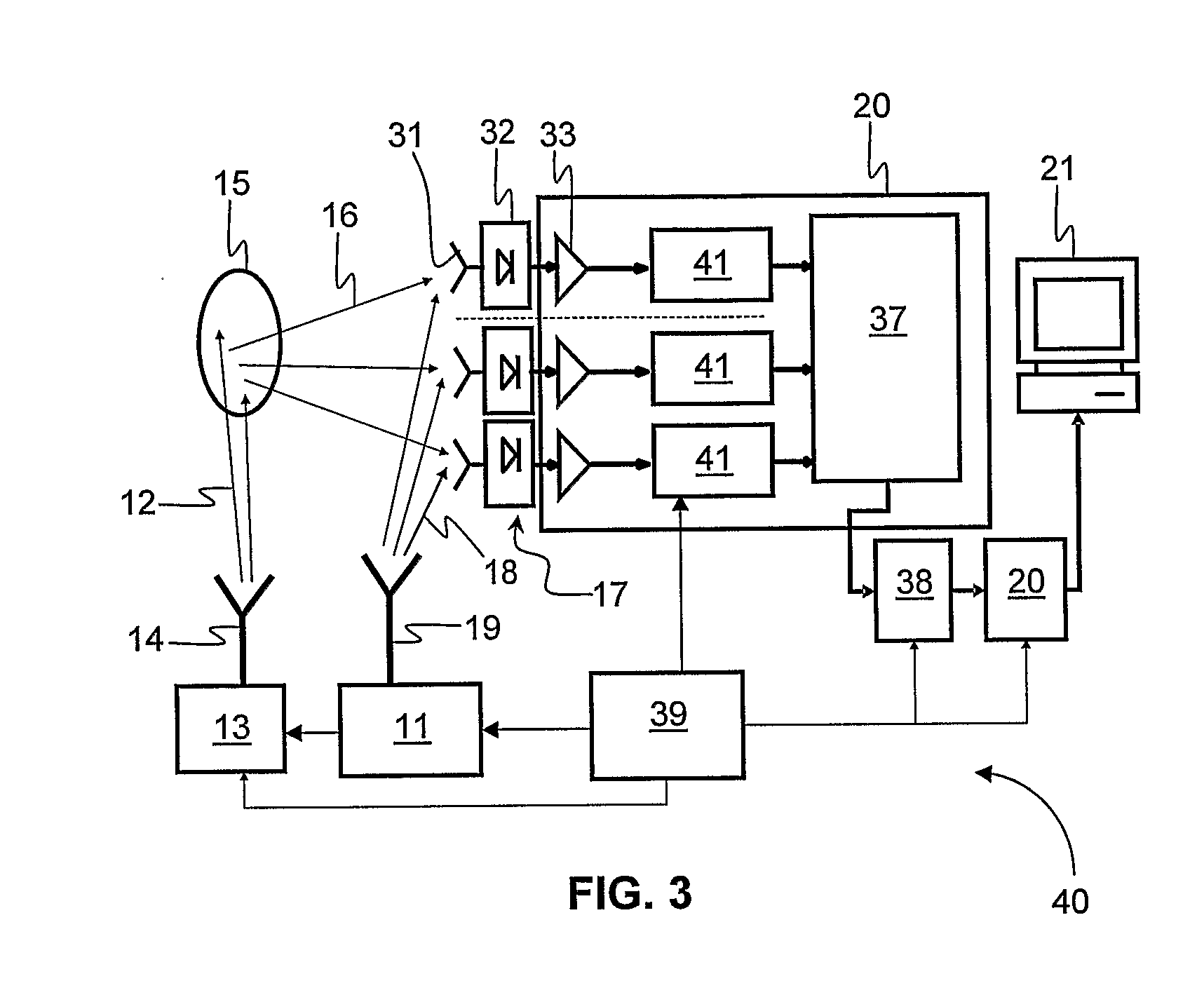
[0030]FIG. 3 shows schematically a holographic surveillance system 40 according to the invention, wherein components having similar functionality to those shown in FIG. 2 are referenced by identical reference numerals. For the most part, the system 40 is identical to the system 30 except that in FIG. 3, the preamplifiers 33 are connected 1-to-1 to respective ADCs 41 such that the signals are sampled synchronously and converted from analog to digital in parallel for each antenna. The digital signals are then fed to the digital signal processor 20 where they are digitally processed and converted into a holographic image. The timing unit 39 feeds timing signals to the microwave generator 11 and to the modulator 13 as in FIG. 2. Likewise, timing signals are fed to the ADCs 41, there being no need for sample and hold circuits in this configuration.
[0031]Having described the broad functionality of some working embodiments, some more detailed description will now be given of the main compo...
PUM
 Abstract
Description
Claims
Application Information