
ZScreen® modulator with wire grid polarizer for stereoscopic projection

a polarizer and stereoscopic technology, applied in the field of polarization switch or modulator, can solve the problems of dye stuff sheet polarizers not achieving the desired contrast ratio performance, polarizers will fade in time and lose their desirable characteristics, and polarizers will quickly degrade, so as to achieve the effect of improving performan

Active Publication Date: 2008-12-25
REAID INC
View PDF6 Cites 80 Cited by
  • Summary
  • Abstract
  • Description
  • Claims
  • Application Information

AI Technical Summary

Benefits of technology

The present invention provides a polarization modulator device for use with a projector having a projector lens. The device includes at least one pi-cell or pi-cell electro-optical modulator in combination with a wire grid polarizer mounted proximate the pi-cell(s). The design offers improved performance, particularly in heating, compared with previous designs. The invention also provides a method of projecting stereoscopic images using the device. The technical effects of the invention include improved performance and more efficient use of light energy for projecting stereoscopic images.

Problems solved by technology

Even with the fan the polarizer will fade in time and lose its desirable characteristics because of the fugitive nature of the dyes employed.
Without the fan, the polarizer will quickly degrade when used with a modern theatrical theater projector.
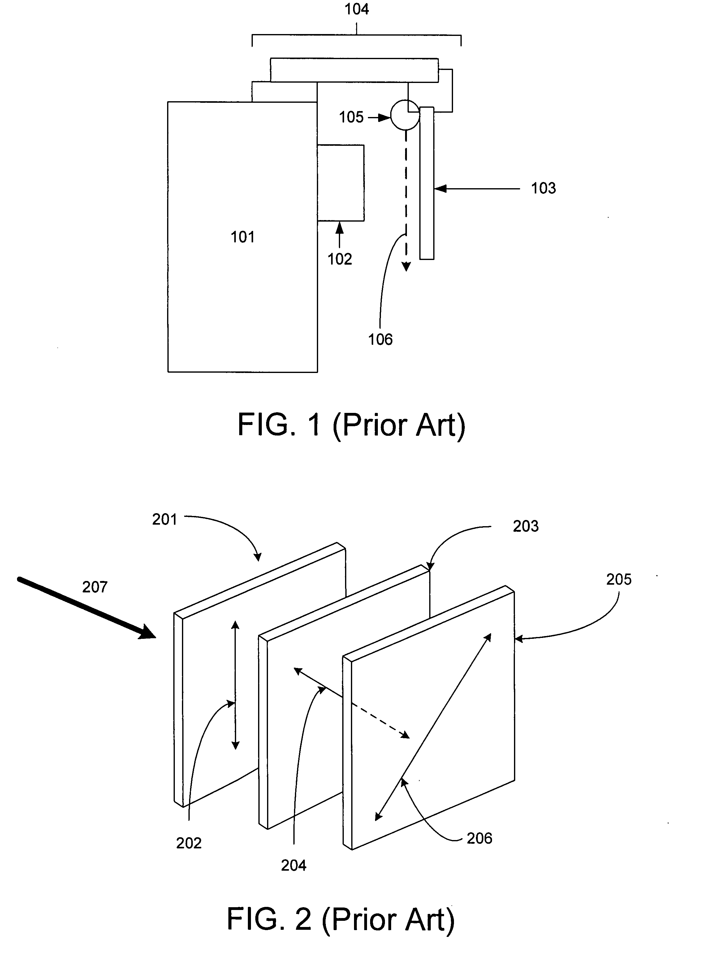
The size of the modulator, dictated by the need to dissipate the radiant flux from the projector, precludes mounting the device to the lens itself because of its bulk and weight and thus must be mounted to the projector body.
Theoretically, a polarizer of this type could achieve a 50% transmission, but in fact, as noted, dye stuff sheet polarizers do not achieve this level of transmission with the desired contrast ratio performance.
Accordingly, the ZScreen device, for the reasons given here, becomes bulky and heavy; it requires larger mounting hardware; it requires a fan; and it needs to be held farther from the projection lens to spread out the luminous flux over a larger surface area to promote cooler operation.

Method used


Image

  • ZScreen® modulator with wire grid polarizer for stereoscopic projection
  • ZScreen® modulator with wire grid polarizer for stereoscopic projection
  • ZScreen® modulator with wire grid polarizer for stereoscopic projection

Examples


Embodiment Construction

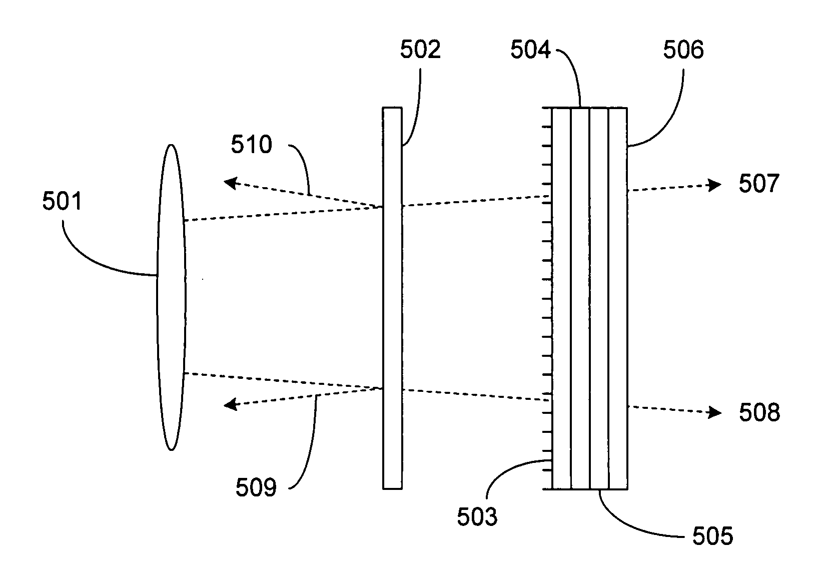
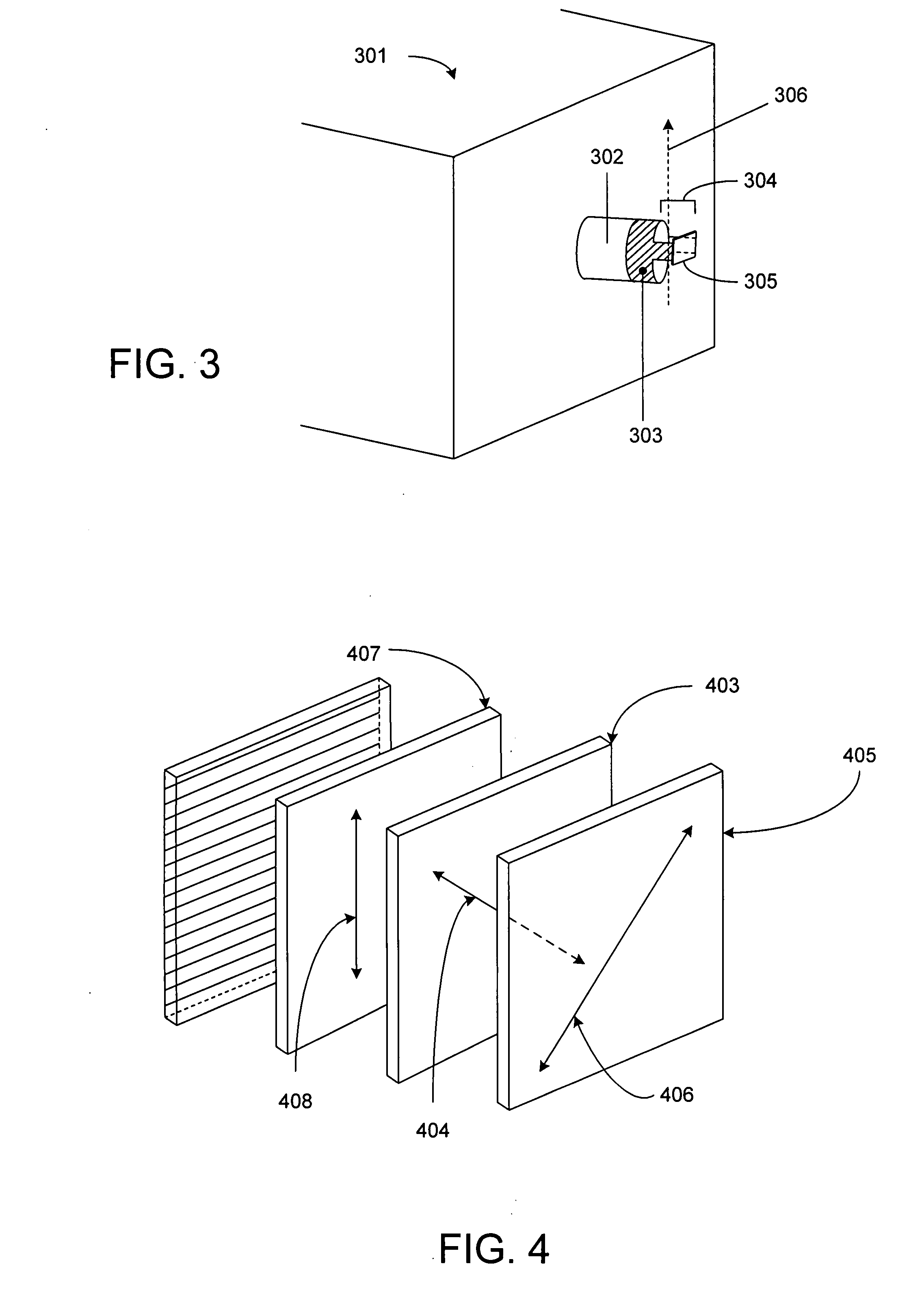
[0019]The present design seeks to increase the optical quality of the projected stereoscopic image by increasing the transmission of the ZScreen modulator through use of a Wire Grid Polarizer (WGP), resulting in a higher efficiency polarization modulator offering both greater transmission and ANSI contrast. In addition the present design reduces the size and weight of the projection ZScreen so as to make a package easier to install and mount directly on a projector lens. By using a wire grid polarizer, the design reduces the complexity of the prior product by eliminating a cooling fan, thus making the device more robust, smaller, and not susceptible to cooling fan failure. Moreover, dyestuff and similar polarizers fade with the passage of time and become less efficient, whereas the use of a WGP maintains polarization efficiency with the passage of time.

[0020]The present design therefore employs a WGP to reduce the size of the device and eliminate the cooling fan. This size and corre...


PUM

PropertyMeasurementUnit
light energyaaaaaaaaaa
polarization transmissionaaaaaaaaaa
sizeaaaaaaaaaa

Abstract

A projection design configured for use with a projector having a projector lens is provided. The device includes at least one pi-cell or pi-cell electro-optical modulator in combination with a wire grid polarizer mounted proximate the pi-cell(s). The design may include a cleanup polarizer between the pi-cell(s) and the wire grid polarizer and optionally a protective window between the wire grid projector and projection lens. The device may be oriented at an angle substantially differing from the axis of the projector lens. The resultant device includes spacing for airflow and can offer improved performance, particularly in heating, over designs previously available.

Description

BACKGROUND OF THE INVENTION[0001]1. Field of the Invention[0002]The invention is generally directed to the art of stereoscopic motion picture projection, and more specifically to a polarization switch or modulator of improved performance characteristics using a wire grid polarizer (WGP).[0003]2. Description of the Related Art[0004]Stereoscopic motion pictures are frequently projected using the polarization method for image selection. An important variation of polarization transmission uses the REAL D / StereoGraphics ZScreen®, which has been described previously in issued and co-pending patents, U.S. Pat. No. 4,792,850 and U.S. patent application Ser. No. 11 / 430,598. The ZScreen modulator is mounted on a projector, and production units are mounted directly to the body of the projector and hung in front of the projection lens.[0005]An important concern in the ZScreen is the sheet polarizer, which has been available as a product for 60 or 70 years. The sheet polarizer is also called an ...

Claims


Application Information

Patent Timeline
Patent Type & Authority Applications(United States)
IPC IPC(8): G02F1/1335G02B30/25
CPCG02B5/3058G02B27/26G02B27/286G03B35/26G02B30/25
Inventor LIPTON, LENNYCOWAN, MATT
Owner REAID INC
Learn More