Laser radar apparatus that measures direction and distance of an object

Active Publication Date: 2008-12-25
DENSO WAVE INC
View PDF9 Cites 56 Cited by
  • Summary
  • Abstract
  • Description
  • Claims
  • Application Information

AI Technical Summary

Benefits of technology

[0008]It is an object of the present invention to provide a laser radar apparatus that has an improved beam splitting efficiency and an improved accuracy of detecting the direction of an object and

Problems solved by technology

This conflicts with the tendency of

Method used


Image

  • Laser radar apparatus that measures direction and distance of an object
  • Laser radar apparatus that measures direction and distance of an object
  • Laser radar apparatus that measures direction and distance of an object

Examples


Example

First Embodiment

[0030]Referring to FIGS. 1-3, a laser radar apparatus according to a first embodiment of the present invention will be described.

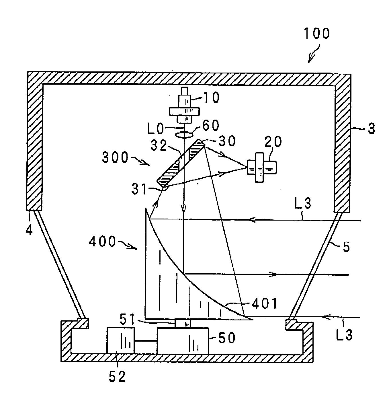
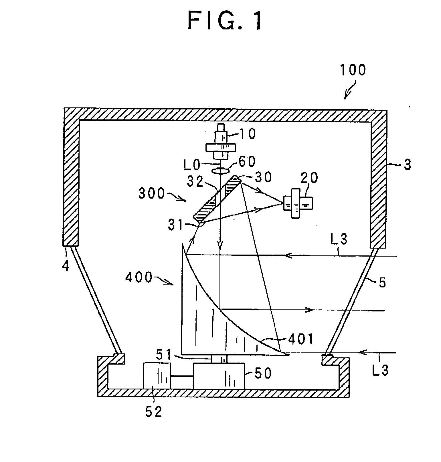
[0031]FIG. 1 is a schematic view of the laser radar apparatus 100 according to the first embodiment of the present invention.

[0032]As shown in FIG. 1, the laser radar apparatus 100 includes a laser diode 10 and a photo diode 20. The laser radar apparatus 100 is designed to detect the direction to an object located in a measurement range, if it exists, and the distance of the object from the apparatus based on the difference of the phases of an outgoing light L0 emitted by the laser diode 10 and an incoming light L3 that is reflected back by the object and received by the photo diode 20, or the time of flight between the emission of an outgoing light L0 and reception of an incoming light L3 utilizing the speed of light. In this embodiment, the laser diode 10 emits a laser pulse.

[0033]The laser diode 10 emits a laser pulse having an axis ther...

Example

Second Embodiment

[0069]Referring to FIGS. 4-7, a laser radar apparatus according to a second embodiment of the present invention will be described.

[0070]FIG. 4 is a schematic view of the laser radar apparatus 100A according to the second embodiment of the present invention.

[0071]In the present embodiment, the differences from the previous embodiment are based on the presence of beam splitting means 80 and an improved method for operating a control device 82 and a memory 84. Thus, detailed discussion about the constituents of the laser radar apparatuses having the same function and the structure with those used in previous embodiment will be omitted.

[0072]As shown in FIG. 4, the laser radar apparatus 100A according to the present embodiment includes a mirror assembly 300A, a control device 82, and a memory 84. The control device 82 and the memory 84 correspond to control means and memorizing means, respectively. In the present embodiment, the projection optical system includes the la...

Example

Third Embodiment

[0096]Referring to FIG. 8, a laser radar apparatus 100B according to a third embodiment of the present invention will be described.

[0097]FIG. 8 is a schematic view of the laser radar apparatus 100B according to the third embodiment of the present invention.

[0098]In the present embodiment, the differences from the first embodiment are based on the presence of a first cover member 92 having a first slit 93 and a second cover member 95 having a second slit 96. Thus, detailed discussion about the constituents of the laser radar apparatuses having the same function and structure with those used in the first embodiment will be omitted.

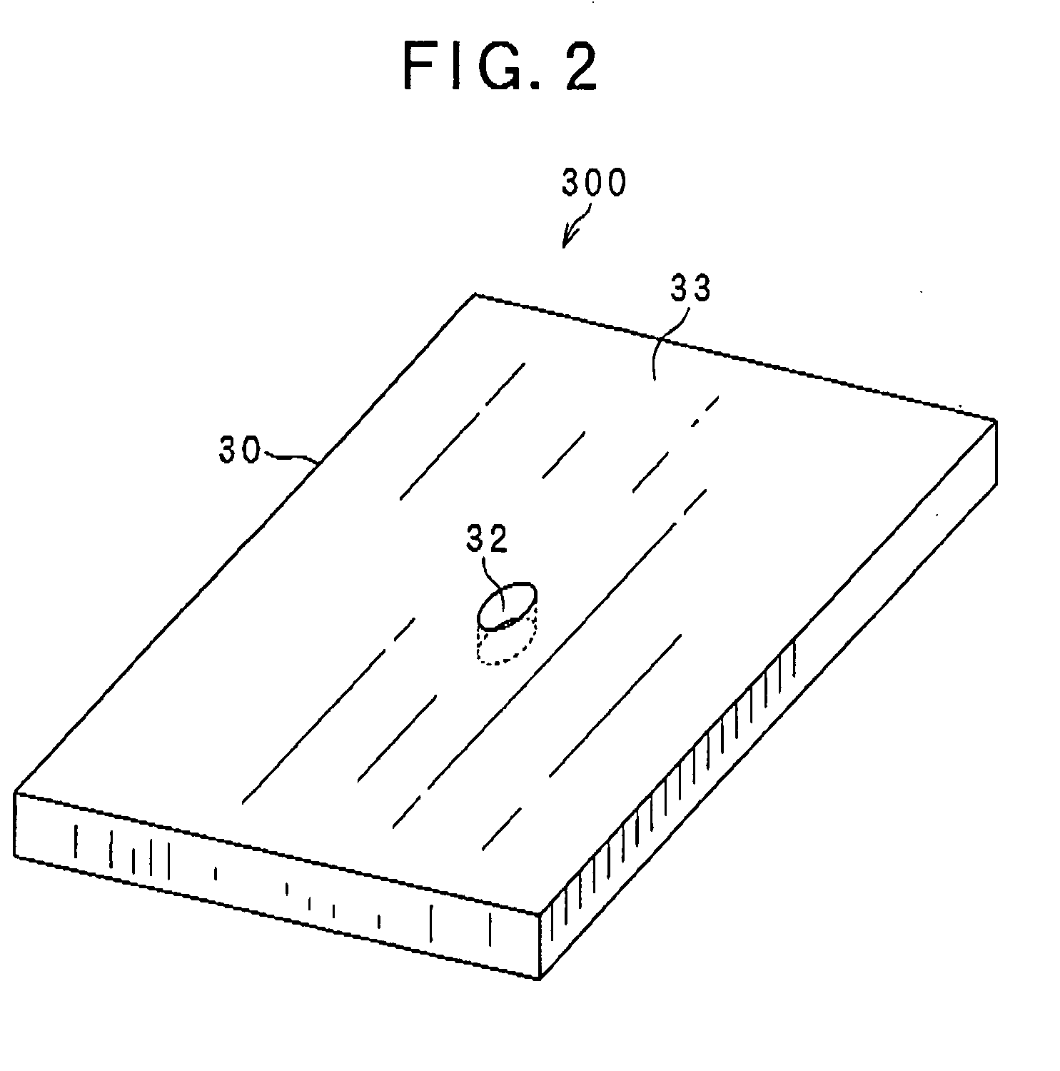
[0099]As in the case of the first embodiment, the mirror 30 is arranged at a predetermined angle, for example, of about 45 degrees with respect to the axis of the outgoing laser beam L0. Further, the mirror 30 has the through-hole 32 through which the outgoing laser beam L0 passes without any loss of intensity thereof. Further, the mirror 30 ...


PUM


Abstract

There is provided a laser radar including laser beam generating means, photo detecting means, a mirror, light deflecting means, and rotation driving means. The laser beam generating means emits a laser beam having an axis thereof. The photo detecting means detects a reflected laser beam that is reflected back by an object. The mirror includes a through-hole that passes the laser beam and a reflecting surface that reflects a reflected laser beam reflected back by the object toward the photo detecting means. The light deflecting means deflects the laser beam toward a measuring region and reflects the reflected laser beam from the object toward the mirror. The rotation driving means rotates the light deflecting means so as to direct the laser beam toward the measuring region.

Description

CROSS REFERENCE TO RELATED APPLICATION[0001]The present application relates to and incorporated by reference Japanese Patent Applications 2007-027167 filed on Feb. 6, 2007 and 2007-293225 filed on Nov. 12, 2007.BACKGROUND OF THE INVENTION[0002]1. (The Field of the Invention)[0003]The invention relates to a laser radar apparatus and a method for measuring both the direction of an object and the distance to an object from the apparatus using a laser beam.[0004]2. (Description of the Prior Art)[0005]As laser radar apparatus capable of measuring both the direction of an object and the distance to an object from the apparatus, there is a known apparatus such as disclosed by Hoashi et al. in Japanese Patent No. 2789741.[0006]The laser radar apparatus of Hoashi et al. includes a laser beam generating means for emitting a laser beam or a laser pulse serving as an outgoing light into a measurement range, the outgoing light having an optical axis thereof, a photo detecting means for detecting...

Claims


Application Information

Patent Timeline
IPC IPC(8): G01C3/08
CPCG01S7/4812G01S7/4813G01S7/4817G01S17/42G02B26/0816
Inventor OKADA, MASANORITANAKA, HIDEYUKIKONOSU, KOJINOJIRI, TADAO
Owner DENSO WAVE INC
Why Eureka
Try Eureka