Magnetic head for perpendicular magnetic recording and method of manufacturing same

US20080316653A1Active Publication Date: 2008-12-25HEADWAY TECH INC

Image

  • Magnetic head for perpendicular magnetic recording and method of manufacturing same
  • Magnetic head for perpendicular magnetic recording and method of manufacturing same
  • Magnetic head for perpendicular magnetic recording and method of manufacturing same

Examples


first embodiment

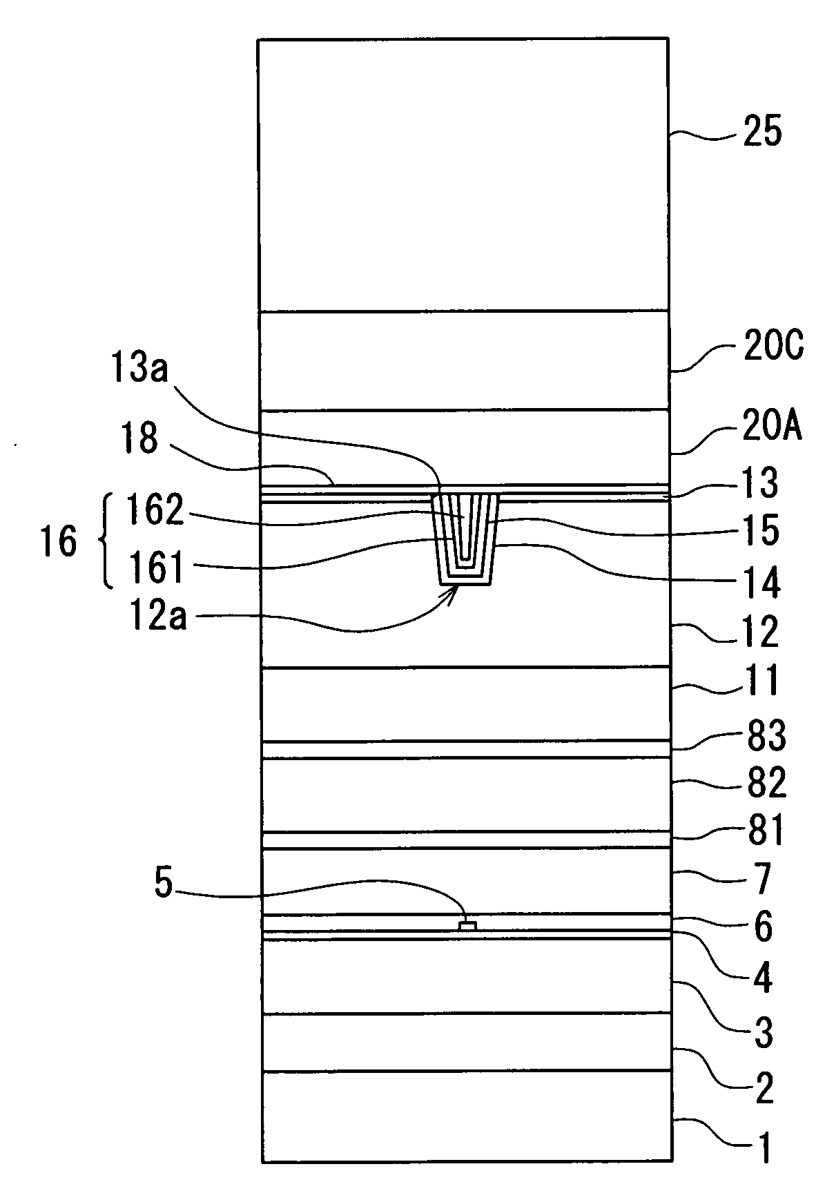
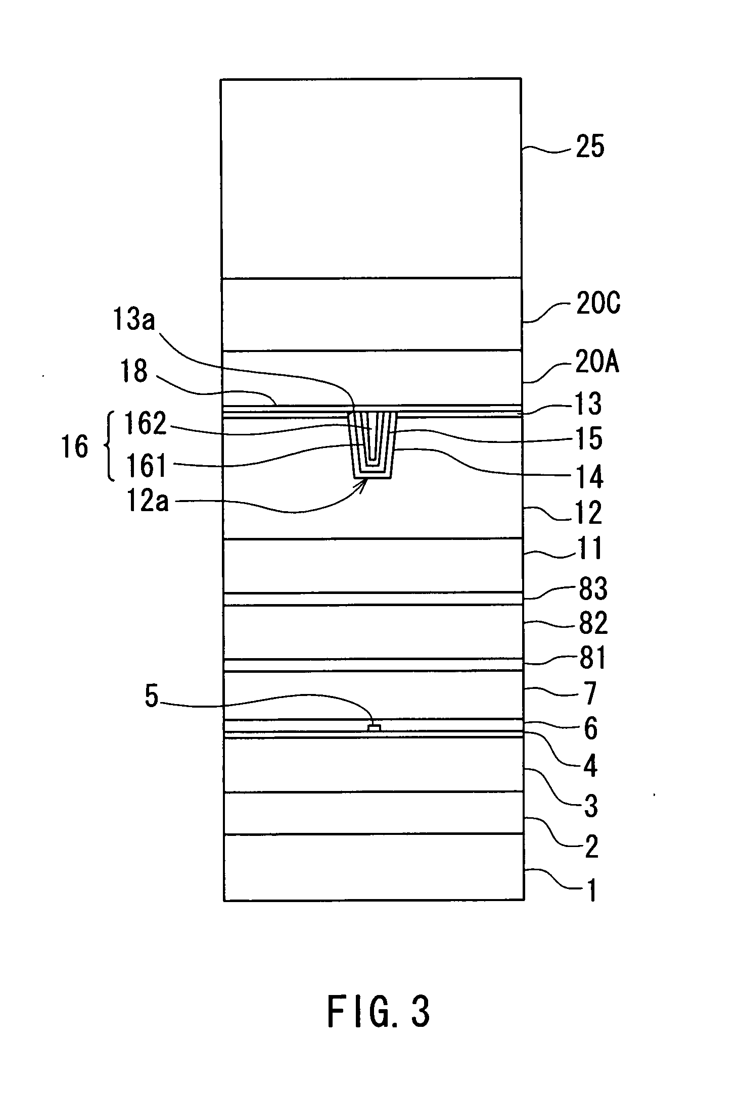
[0066]Preferred embodiments of the invention will now be described in detail with reference to the drawings. Reference is now made to FIG. 3 and FIG. 4 to describe the configuration of a magnetic head for perpendicular magnetic recording of a first embodiment of the invention. FIG. 3 is a front view of the medium facing surface of the magnetic head for perpendicular magnetic recording of the embodiment. FIG. 4 is a cross-sectional view for illustrating the configuration of the magnetic head for perpendicular magnetic recording of the embodiment. FIG. 4 illustrates a cross section orthogonal to the medium facing surface and the top surface of the substrate. The arrow marked with T in FIG. 4 shows the direction of travel of a recording medium.

[0067]As shown in FIG. 3 and FIG. 4, the magnetic head for perpendicular magnetic recording (hereinafter simply called the magnetic head) of the embodiment includes: a substrate 1 made of a ceramic material such as aluminum oxide and titanium car...

second embodiment

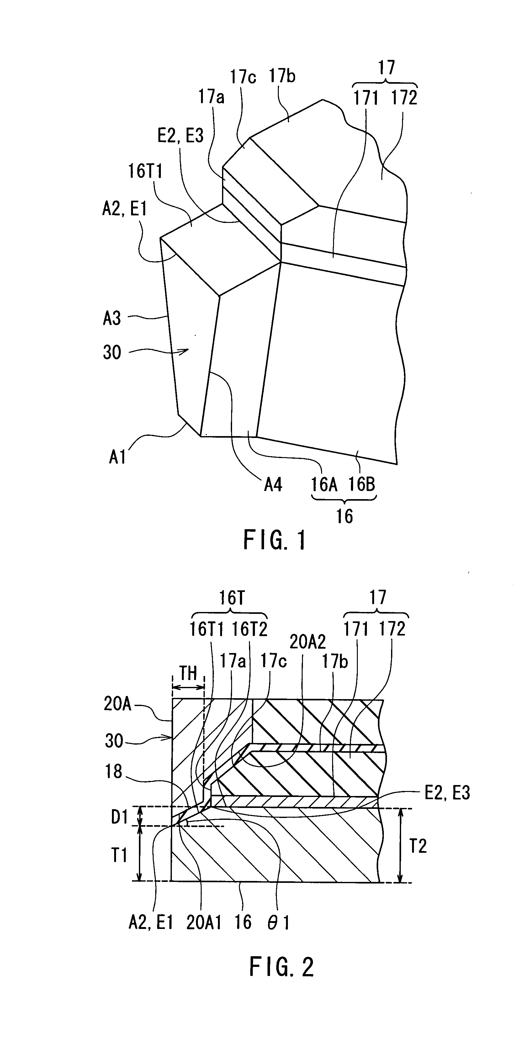
[0147]A magnetic head and a method of manufacturing the same of a second embodiment of the invention will now be described. Reference is now made to FIG. 19 and FIG. 20 to describe the configuration of the magnetic head of the second embodiment. FIG. 19 is a perspective view of part of each of the pole layer 16 and the nonmagnetic layer 17 of the embodiment near the medium facing surface 30. FIG. 20 is a cross-sectional view of part of each of the pole layer 16, the nonmagnetic layer 17, the gap layer 18 and the shield 20 of the embodiment near the medium facing surface 30. In the second embodiment, the inclined surface 17c of the nonmagnetic layer 17 is smaller in area as compared with the first embodiment. The nonmagnetic layer 17 can be free of the inclined surface 17c. In this case, a ridgeline is formed between the end 17a and the top surface 17b.

[0148]The first layer 20A of the shield 20 has: a first surface 20A1 disposed such that the gap layer 18 is sandwiched between the f...


PUM


Abstract

A magnetic head includes: a pole layer; a nonmagnetic layer disposed on part of the top surface of the pole layer; a gap layer disposed on the pole layer and the nonmagnetic layer; and a shield disposed on the gap layer. The top surface of the pole layer includes: a first portion having a first edge located in a medium facing surface and a second edge opposite thereto; and a second portion located farther from the medium facing surface than the first portion and connected to the first portion at the second edge. The first portion is inclined with respect to a direction orthogonal to the medium facing surface so that the distance from a substrate increases with increasing distance from the medium facing surface. The nonmagnetic layer has a bottom surface touching the second portion, and this bottom surface has an edge located at the second edge.

Description

BACKGROUND OF THE INVENTION[0001]1. Field of the Invention[0002]The present invention relates to a magnetic head for perpendicular magnetic recording that is used for writing data on a recording medium by means of a perpendicular magnetic recording system, and to a method of manufacturing such a magnetic head.[0003]2. Description of the Related Art[0004]The recording systems of magnetic read / write devices include a longitudinal magnetic recording system wherein signals are magnetized in the direction along the surface of the recording medium (the longitudinal direction) and a perpendicular magnetic recording system wherein signals are magnetized in the direction orthogonal to the surface of the recording medium. It is known that the perpendicular magnetic recording system is harder to be affected by thermal fluctuation of the recording medium and capable of implementing higher linear recording density, compared with the longitudinal magnetic recording system.[0005]Typically, magneti...

Claims


Application Information

Patent Timeline
25 Dec 2008
Publication
US20080316653A1
IPC
G11B5/10
CPC
G11B5/1278; G11B5/3116
Inventors
SASAKI, YOSHITAKA; ITOH, HIROYUKI